


Several display features can be helpful when you are setting up contact in your model, including:
| Controlling Transparency for Contact Regions |
| Displaying Contact Bodies with Different Colors |
| Hiding Bodies Not Scoped to a Contact Region |
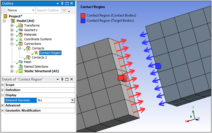
The Display category is available for edge contact on 2D surface bodies and face contact on 3D bodies. You can visualize the normal direction of each element in the Contact Region by using the Element Normals property, which can be set to (default) or (displays normal directions for each element).
As needed, you can invert the normal direction using the Flip Contact Normals and/or Flip Target Normals property in the Geometric Modification category for 2D edges, or the Reverse Shared Contact Normal and/or Reverse Shared Target Normal properties in the Scope category for shared 2D edges and 3D faces.
Important:
If your analysis includes 2D surface bodies in contact and the edge normal directions do not adhere to the right-hand rule, that is, the normals appear to be in the wrong direction, you can use the Flip Contact Normals and/or the Flip Target Normals properties to reorient the edge directions.
If a Contact Region is defined by nodal scoping, element normals may not be visible for contact elements.
When a Contact Region is scoped to shell faces and the Contact Shell Face or the Target Shell Face properties are set to , the application does not draw the arrows for the element normals (even if the property is set to ).
Controlling Transparency for Contact Regions
As shown below, you can graphically highlight an individual contact region.
Refresh the page, as needed, to see the following animation. View online if you are reading the PDF version of the help.
Select a contact region to highlight the bodies in that region.
Highlighting is due to internal transparency settings:
Transparency is set to 0.8 for bodies in selected contact region.
Transparency is set to 0.1 for bodies not in selected contact region(s).
You can change the default transparency values in using the Connections settings of the Options dialog box.
You can disable the contact region highlighting feature in either the Details pane of a contact group branch, or using the context (right mouse click) menu on a contact region or contact group branch, and choosing .
Use the preference (Options > Graphics) to make model edges transparent.
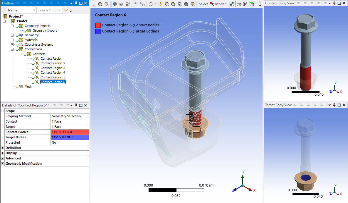
Displaying Contact Bodies with Different Colors
Contact and target bodies are displayed using default colors (red and blue). You can change the display color using the option in the Annotations group to display each contact using a color chosen at random each redraw.
Hiding Bodies Not Scoped to a Contact Region
You can hide all bodies except those that are scoped to a specific contact region.
To Hide All Bodies Not Scoped to a Contact Region:
Select the Contact Region object whose bodies you do not want to hide.
Right-click to display the context menu.
Select in the menu. All bodies are hidden except those that are part of the selected contact region.