


The Bearing Load boundary condition applies a distributed load to the interior of a cylindrical surface to represent the effect of a shaft or pin acting on a bearing surface. The load simulates radial forces only and is applied normal to the surface in the radial direction based on a specified coordinate system. If the Mechanical application detects any component of the load in the axial direction, the application stops the solution process and issues an error message.
Load Distribution
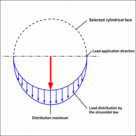
The application applies the bearing load as a nonuniform pressure distribution over a portion of the cylindrical surface. The distribution follows a sinusoidal (cosine) variation, with the maximum pressure occurring along the load application direction and decreasing smoothly along the surface away from this direction.
Note: This load distribution approach is consistent across Ansys Mechanical and Ansys Discovery.
Bearing Load Distribution on a Cylindrical Surface
As illustrated, the load is applied over a portion of the cylindrical surface, with a maximum value in the direction of the applied load and a sinusoidal decrease along the circumference.
Usage Notes
- Geometry Scoping
If the CAD system splits a cylindrical surface into multiple faces, select all corresponding faces when applying the load.
- Multiple Cylinders
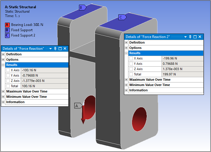
Scope each cylindrical surface with its own Bearing Load condition. If you apply a single Bearing Load to multiple cylinders, the application distributes the load based on each cylinder’s surface area. The following example shows two cylinders, where the cylinder on the right is twice the length of the cylinder on the left. As shown, reaction forces are proportional to the area ratio of the scoped surfaces.
- Multistep Load Definition
You cannot define the magnitude using tabular or functional data. For multi-step analyses, specify a constant or ramped value for each step, where each step has a single load value.
This page includes the following topics:
Analysis Types
Bearing Load is available for the following analysis types:
Dimensional Types
The supported dimensional types for the Bearing Load boundary condition include:
3D Simulation. For vector-based loading on a cylindrical face or geometric axis, you define the radial direction by selecting a different piece of geometry on your model that allows you to modify the Direction in the desired direction.
2D Simulation. The Bearing Load boundary condition applies a variable distribution of force to a circular edge.
Geometry Types
The supported geometry types for Bearing Load include:
Solid
Topology Selection Options
The supported topology selection options for the Bearing Load boundary condition include:
Face. If the loaded face enlarges (for example, due to a change in parameters), the total load applied to the face remains constant, but the pressure (force per unit area) decreases.
Edge: Supported for 2D only.
Element Face: Supported for 3D only.
Define By Options
The supported Define By options for the Bearing Load boundary condition include:
. You define the radial direction for your vector load by selecting a piece of geometry on your model that provides the ability to specify the direction correctly.
The vector load definition displays in the Annotation legend with the label Components. The Magnitude and Direction entries, in any combination or sequence, define these displayed values. These are the values sent to the solver.
. While loads are associative with geometry changes, load directions are not.
Magnitude Options
The Magnitude options for Bearing Load include:
Constant
Tabular (Time Varying)
Note:Although loading across multiple steps may appear as an application of tabular loading, you cannot set the magnitude of a Bearing Load in terms of either tabular or functional data. You must set a constant or ramped magnitude for each step such that one value corresponds to each step.
After modifying a Bearing Load using the Tabular Data window, the Magnitude property displays "Tabular Data." To reapply a constant magnitude, enter a desired value directly in the property field.
Tabular (Step Varying): Supported for Static Structural analysis only.
Applying a Bearing Load Boundary Condition
To apply a Bearing Load:
On the Environment Context tab, open the Loads drop-down menu and select Bearing Load. Alternatively, right-click the Environment tree object or in the Geometry window and select Insert>Bearing Load.
Define the Scoping Method as either Geometry Selection or Named Selection and then specify the geometry.
Select the method used to define the Bearing Load: Vector (default) or Components.
Define the Magnitude, Coordinate System directional loading, and/or Direction of the load based on the above selections.
Note:If you scope this load using the Element Face or Node selection options, you must use either of these options to properly specify the Direction property. That is, select the Direction property field (Click to Define), make sure that either the Element Face or the Node selection option is active, and then define the desired direction.
The Direction property is not associative and does not remain joined to the entity(s) selected for its specification. Therefore, this direction is not affected by geometry updates, part transformation, or the Configure tool (for joints).
Details Pane Properties
The selections available in the Details pane are described below.
| Category | Property/Options/Description |
|---|---|
| Scope | Scoping Method: Options include:
|
| Definition |
Type: Read-only field that describes the object - Bearing Load. Define By, options include:
Suppressed: Include ( - default) or exclude () the boundary condition. |
|
Load Vector Controls (Modal only) |
Load Vector Assignment: Options include (default) and . Load Vector Number: Specify an integer value greater
than Important:
|
Mechanical APDL References and Notes
The following Mechanical APDL commands, element types, and considerations are applicable for this boundary condition.
Force is applied using the SF,,PRES command.
Element types include:
API Reference
For specific scripting information, see the Bearing Load section of the ACT API Reference Guide.