


Note 1:
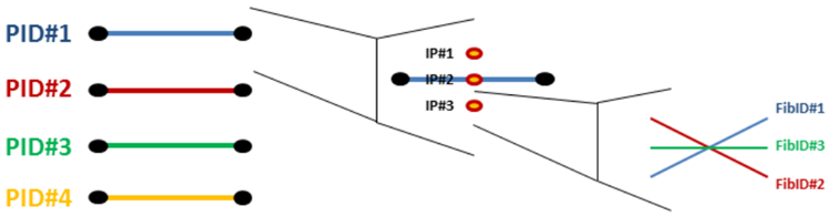
As shown in Figure 5.3: Number of stacks, integration points and fiber IDs for *MAT 249, *MAT 249 outputs several fibers at each integration point. This must be considered in NTHICK or in the respective averaging options. In the example below, the source file consists of four stacked shell elements (Part 1 - 4), with three integration points through the thickness each, having three fibers each. A complete mapping for *ELEMENT SHELL COMPOSITE therefore leads to a total of 36 (4x3x3 ) layers and integration points. Averaging can be done as follows:
ThroughThicknessAveraging = YES
NumberOfFiberBundles= 12
FiberBundle#1:
MatID=1001
Lay= 1, IP= 1, Fib= 1
Lay= 1, IP= 2, Fib= 1
Lay= 1, IP= 3, Fib= 1

...

FiberBundle#4:
MatID=1004
Lay= 2, IP= 1, Fib= 1
Lay= 2, IP= 2, Fib= 1
Lay= 2, IP= 3, Fib= 1

...

FiberBundle#12:
MatID=1012
Lay= 4, IP= 1, Fib= 3
Lay= 4, IP= 2, Fib= 3
Lay= 4, IP= 3, Fib= 3
This leads to a reduced number of twelve layers and integration points for *ELEMENT SHELL COMPOSITE after the mapping.
Each layer may have the same material ID or different material IDs.
Note 2:
The main purpose of fiber bundle handling is explained in the previous note. If the target material model is defined to handle the *MAT 249 IHIS=1 option, fiber averaging can encapsulate up to three distinct fiber directions. The averaging of the directions of the fibers on the target side can be coupled using different source PIDs, through thickness integration points (IPs) and fibers.
Take, for example, a mapping process with two source PIDs, 10 and 20, which are defined as SourcePID#1 and SourcePID#2, respectively. Both source meshes have three through thickness IPs and all three fibers are provided in mesh *INITIAL STRESS SHELL fields at the respective history variable positions. It is necessary to map fiber directions on to five (NTHICK=5) through thickness target IPs, and the fiber bundles are defined as follows:
ThroughThicknessAveraging = YES
NumberOfFiberBundles= 5
FiberBundle#1:
MatID=28
Lay= 1, IP= 1, Fib= 321
Lay= 1, IP= 2, Fib= 321
Lay= 1, IP= 3, Fib= 321

FiberBundle#2:
MatID=82
Lay= 1, IP= 1, Fib= 123
Lay= 1, IP= 2, Fib= 231
Lay= 1, IP= 3, Fib= 312

FiberBundle#3:
MatID=28016
Lay= 1, IP= 1, Fib= 321
Lay= 1, IP= 2, Fib= 321
Lay= 1, IP= 3, Fib= 321
Lay= 2, IP= 1, Fib= 123
Lay= 2, IP= 2, Fib= 123
Lay= 2, IP= 3, Fib= 123

FiberBundle#4:
MatID=16
Lay= 2, IP= 1, Fib= 123
Lay= 2, IP= 2, Fib= 123
Lay= 2, IP= 3, Fib= 123

FiberBundle#5:
MatID=61
Lay= 2, IP= 1, Fib= 321
Lay= 2, IP= 2, Fib= 321
Lay= 2, IP= 3, Fib= 321
The first fiber bundle averaging uses SourcePID#1 information and the result is saved on the first through-thickness target IP from the shell bottom. The Fib definition indicates that the routine averages the first fibers of all source through-thickness IPs and stores the average as the first fiber direction for the target mesh.
The same methodology is followed for the second and third fibers. As a result, the average of the first source fibers are stored in the first target fiber position, the average of the second source fibers are stored in the second target fiber position, and the average of the third source fibers are stored in the third target fiber position.
The second fiber bundle averages the third fiber of source IP#1, the first fiber of source IP#2 and the second fiber of source IP#3 and stores the average in the first fiber positions of the second target through-thickness IP from the shell bottom. Similarly, the second target fiber direction is computed using the second fiber of IP#1, the third fiber of IP#2 and the first fiber of IP#3.
The third fiber bundle uses both source PIDs to compute target fiber data. The first target fiber direction of the third target through thickness IP from the shell bottom is computed using the first fibers of all IPs of SourcePID#1 and the third fibers of all IPs of SourcePID#2. The third target fiber direction is similar to the first, but other way around. The second target fiber direction is computed using all second source fiber data from all IPs of both source PIDs.
Fiber bundle material IDs are assigned to the respective through-thickness integration points in the *ELEMENT SHELL COMPOSITE( LONG) keyword.
Note 3
A specific clustering option has been implemented for the ARENA2036 Project - Digital Finger Print. The option aims to modify *ELEMENT SHELL COMPOSITE(LONG) integration point material IDs of certain target mesh elements, which are found using source mesh.
The mapping options should be defined as follows:
Algorithm=ElementSizeSearchRadius
Shell_Option=Composite (or, Composite Long)
NPLANE=<INT>
NTHICK=<INT>
MapStress=NO
MapStrain=NO
MapThickness=NO
NumIterations=<INT>
ClusterID#<INT>=&PID<INT>,<OPTION>,<DOUBLE>,<DOUBLE>,<INT>
The integer on the left hand side indicates the target PID, to which clustering should be applied. The &PID option is supported only for this special case and the following integer defines the source PID to consider for clustering. <OPTION> can be ADDPID or AVG. The ADDPID option modifies the existing material ID by adding a user-defined value. The AVG option overwrites the existing material ID using the user-defined value. The following two <DOUBLE> entries have no effect on the routine, and any values can be defined that satisfy the format. The last <INT> value represents the user-defined value.