


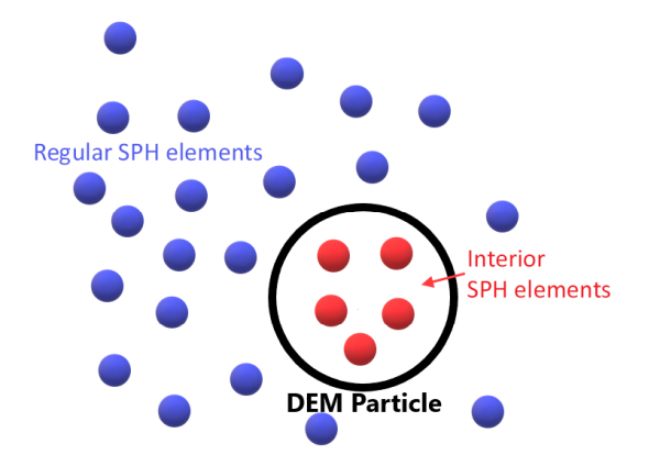
The SPH method holds the ability to handle solid-fluid flows by combining the SPH and DEM approaches. Assuming that the DEM particles are much larger than the mean inter-particle spacing for the SPH elements, the solid-fluid interaction is achieved by placing SPH elements in the interior of the DEM particles, as shown in Figure 3.1: SPH-DEM interaction.. These interior SPH elements have an associated artificial mass, density, and velocity.
The interior SPH elements move and rotate with the solid DEM particle and are initialized with the same initial density used for the SPH elements that represent the fluid phase, evolving in time in the same manner as the fluid SPH elements.
Another point about the DEM-SPH coupling is that, for all inlets, the SPH elements are activated in batches and are gradually released into the simulation over a certain period of time, however they are activated all at once. The ones that are not yet released from the inlet, remain in a state in which they are not still visible but can interact with other SPH elements, and also with DEM particles. In cases with mixed DEM and SPH injections at the same inlet, forces may be detected acting over some DEM particles, due to the presence of those SPH elements that are active, but not yet released, that begin to interact with the falling DEM ones. This interaction cannot be removed because it would make it infeasible to have mixed inlets, in which that interaction is necessary.
Note: In a SPH-DEM simulation within Ansys Rocky Software, when a Particle Assembly or Custom Polyhedron is created, it is necessary to ensure that the SPH size is configured to support at least one kernel radius spanning along the minimum feature size of that geometry.
Important: SPH surface tension models are not applied to SPH-DEM interactions, only to SPH-SPH and SPH-wall interactions. By default, DEM-SPH interactions will behave as completely hydrophobic with a surface angle equal to 180 deg.
As stated in previous section, in a SPH-DEM we have SPH linked and free elements, i.e., associated with a DEM particle and one not associated with a DEM. However, for a flexible shell we have junctions forming the particle (shell), which gives a more complex interaction between SPH and DEM entities.
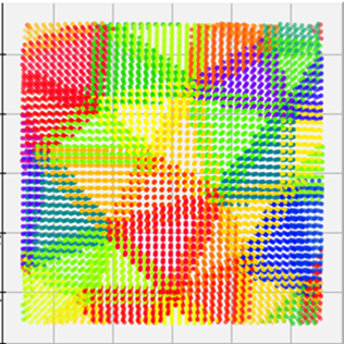
Exclusively for flexible shells, overlapping linked shell elements are allowed to be generated at the overlapping rounded parts of the sphero-triangles that form the shell, see Figure 3.2: Representation of sphero-triangles.. When those sphero-triangles separate of each other due joint deformations, the presence of multiple linked elements prevents to certain extent the passage of fluid elements. In that approach, the mass of the linked elements is assigned dynamically according to its local distribution. In that way, when those elements are close to each other or even overlapping (as in the undeformed position) the assigned mass value will be low. Conversely, when they get separated, the mass value will increase.
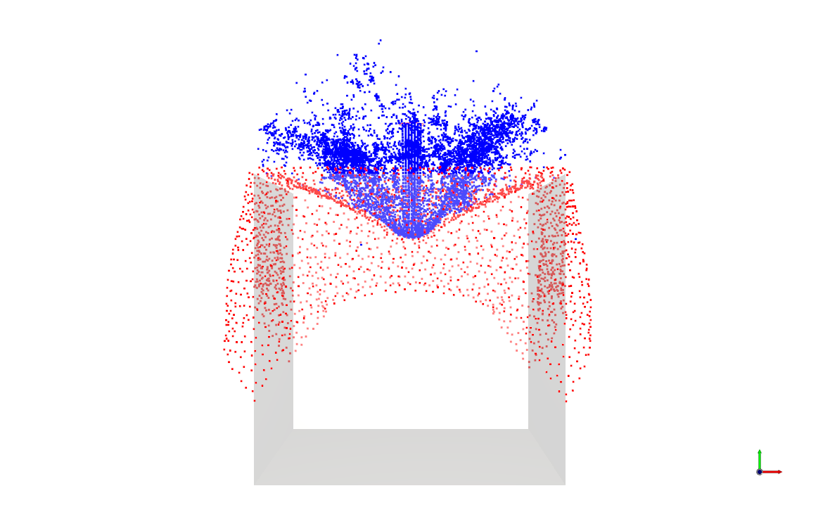
Therefore, it is important to check the joint deformations when performing SPH-DEM simulations. On Rocky, the joint deformations of shell particles can reach up to about 100% of the SPH size don't causing any fluid leaking, such as in Figure 3.3: Example of SPH-DEM simulation without leaking..
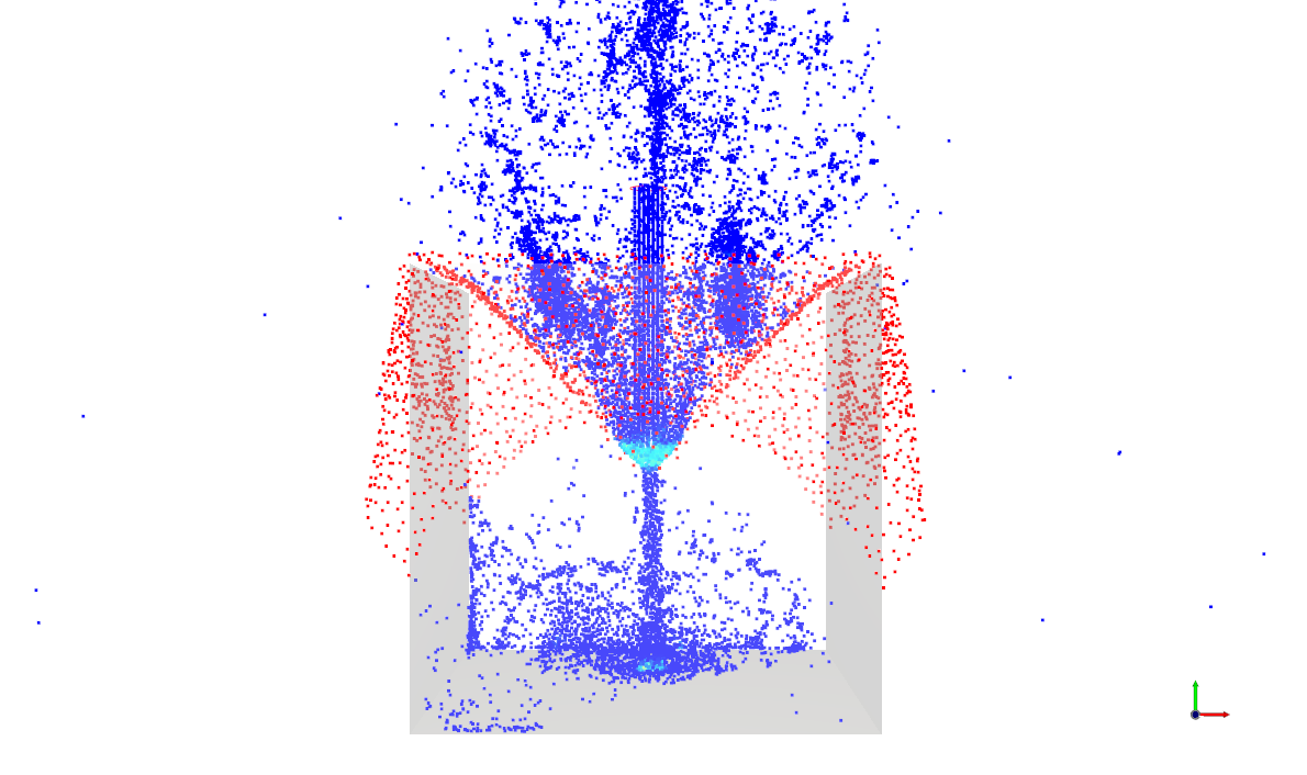
If the joint deformations surpass the SPH size, leaking can be observed. As explained before, with larger joint deformations, spaces will be created. Consequently, SPH elements could pass through these spaces in the flexible shell.
The main feature of the SPH-DEM Interaction Statistics are the three scalars that can be enabled: Fluid Force and Flow-Induced Torque and Heat Transfer (from SPH elements to DEM particles). These statistics scalars are accumulated during the calculation of forces of SPH elements coupled with a DEM particle. For example, if a DEM particle has 10 linked SPH elements, the SPH Fluid Force scalar will be the sum of the calculated force for those 10 elements. The same goes for Flow-Induced Torque and Heat Transfer. This accumulation of values lasts until it has an output in the solver. When this happens, the values accumulated so far are computed, and the values of these scalars is reset to zero.