

The following topics are available:
This problem shows stress-intensity factor calculations for a center-crack specimen under residual stress field. The solution method automatically converts the residual stress data to equivalent traction load on the crack faces. According to the Bueckner's superposition principle, the stress-intensity factor calculated for this traction load is the same as that for the residual stress load.
The model has the following geometry parameters:
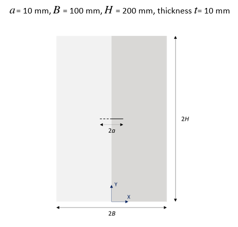
Using symmetry, only one half of the specimen is used for the analysis.
The material is assumed to be isotropic linear elastic with the following properties of typical structural steel:
| Property | Parameter | Value | Unit |
|---|---|---|---|
| Elastic modulus |

| 200000 | MPa |
| Poisson's ratio |

| 0.3 | -- |
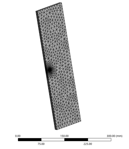
The model is created using the Mechanical application release 2025 R1. The geometry is meshed with 10-noded tetrahedral elements (SOLID187).
A crack is inserted into the model using the Edge Crack option. The element size at the crack front is approximately 0.5 mm. The total number of elements and nodes are 14858 and 23262, respectively (shown in Figure 30: Half-specimen model meshed with tetrahedral elements).
The residual stress data is written in a mesh-independent initial-state file (.ist) using a command snippet.
An INISTATE,READ command (with MeshIndMethod = DOBJ) is issued to read the initial-state file, and a CINT command (CINT,CSFL,INIS,STRE) directs the solver to interpolate the residual stress data to apply traction load on the crack faces.
The solution units are based on the metric system (mm,N).
Symmetry boundary condition is applied on the left face of the half-specimen model (see Figure 31: Boundary Conditions). The model has a fixed support at the bottom face. The front and back faces are constrained along thickness (z-direction) to impose plane strain condition.
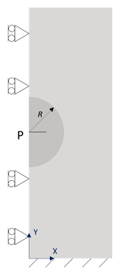
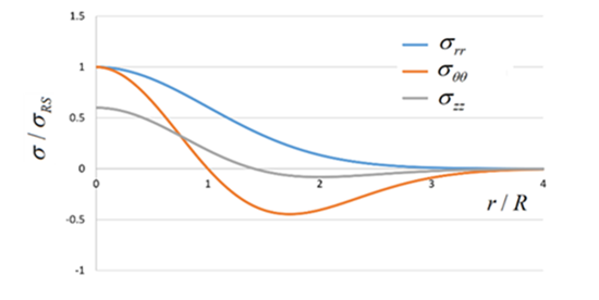
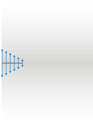
The specimen is considered to have residual stresses developed during processing of the uncracked specimen. The following analytical stress function [9] is assumed for the residual stress distribution around the center point P (see Figure 32: Residual stress distribution around the center of the plate).


This simple function closely resembles the typical residual stress distribution obtained
from local heating of a plate at the center [9]. The
circumferential stress is tensile near the crack location, and changes to compressive after
a certain radial distance  from the center.
The residual stress (in the global Cartesian system) in the vicinity of the crack is
written at discrete locations in a mesh-independent
initial-state file (.ist). The program uses the residual
stress data to calculate the traction load at the crack-faces (shown in Figure 33: Traction load on crack faces (derived from residual stress)). The traction load vector  at any point on a crack face is
  , where
  is the outward normal vector and
  are the residual stress components in the global Cartesian system.
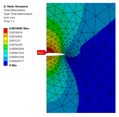
The specified load and boundary conditions induce mode-I fracture. The deformation plot shows symmetric opening of the crack, as expected for mode-I fracture (see Figure 34: Total Deformation).
The traction load at a distance x from the crack center is :

The stress-intensity factor  for varying traction along the crack faces can be evaluated as follows [10]:

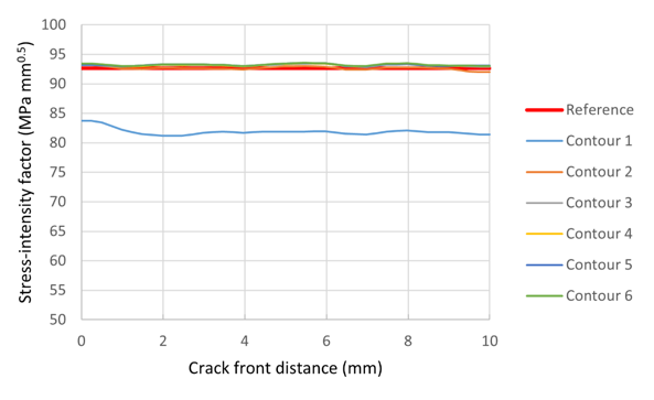
For the given load, the reference solution is  = 92.65 MPa mm0.5.
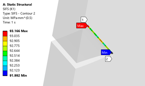
The SIFS (K1) results along the crack front (contours 2 to 6) are close to the reference solution and within 1% tolerance (see Figure 36: Stress-intensity factor K1 compared to reference). The contour-1 results can be ignored due to inaccuracy of the finite element solution so close to the crack front.
Note the following points about the solution:
The automatic conversion of residual stress data to traction load is activated by the command CINT,CSFL,INIS,STRE. It provides a convenient way to calculate stress-intensity factors or J-integral for cracks in residual stress field.
The residual stress data (.ist) is mesh-independent (it is not linked to any mesh nodes). The stress components are written at user-defined locations in the global Cartesian system.
The residual stress data is required only in the vicinity of a crack. The number of stress data points must be sufficient to capture the residual stress variation near the crack. The crack mesh must also be reasonably refined to ensure accurate application of traction loads on the crack faces.
This problem demonstrates a special case where the equivalent traction loads are normal to the crack faces. Note that the solution supports general traction directions calculated from any general residual stress field.
The derived traction load is applied as a step load. Other loads may be ramped or step load.
The traction load derived from residual stress data is not saved in the results file.
If the model contains multiple cracks, issue CINT,CSFL,INIS,STRE for each crack where the residual stress data must be converted to traction load.
The automatic conversion of initial stress data to crack-face traction load can also be used with SMART crack growth. The program automatically applies the traction load on the growing crack faces.
The following files are available for running this benchmark in the Mechanical application (.wbpz) and Mechanical APDL (.dat):