This magnetic cyclic symmetry analysis uses a model of a simplified electrical machine where the model size can be reduced via cyclic boundary conditions.
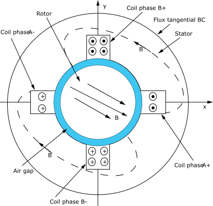
Figure 5.14: Two-Phase Electric Machine - Full Model shows a typical example, the full model of a 2-phase electrical machine.
In the full model, flux parallel boundary conditions can be formulated at the outer surface of the stator frame. If only phase A were excited, the magnetic flux would point in the y direction at x=0 plane; flux parallel condition could be formulated at the x=0 plane, allowing an analysis on a half model in the x>=0 space. Similarly, if only phase B were excited, the magnetic flux would have only x component on the y=0 plane; again, flux parallel could be applied to a half model in the y>=0 plane.
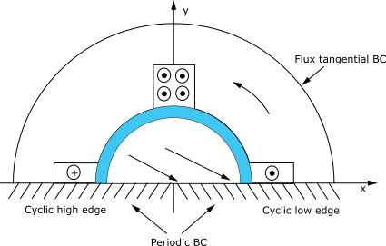
Typically, however, both coils are excited, and no flux parallel conditions could be formulated over the x=0 or y=0 planes. However, due to the cyclic nature of the field, the field pattern repeats itself after 180 degrees. In particular, on the y=0 plane:
By(x) = By(-x)
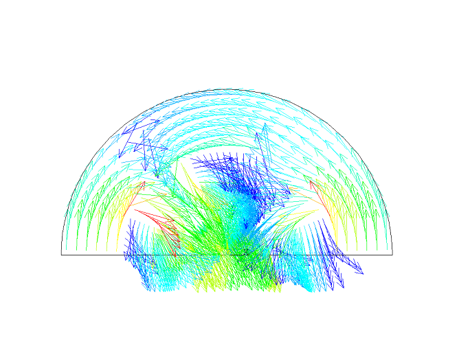
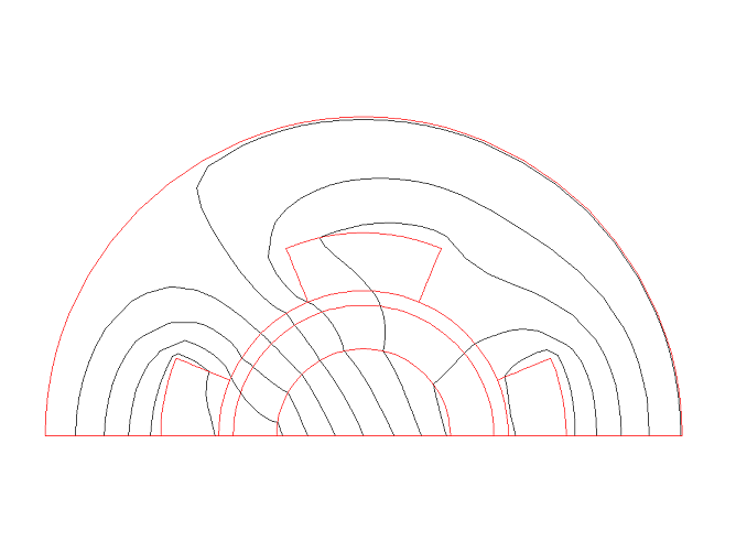
A similar pattern can be observed in Figure 5.15: Two-Phase Electric Machine - Half Model, where the flux lines (equi vector potential lines) are plotted:
Az(x) = - Az(-x)
In this example, the field has a two pole pattern. In general, there are 2p poles; the repetition would take place after 180/p degrees.
The material properties for this analysis are as follows:
Iron relative permeability: 1000
Iron electrical resistivity: 9.579E-8
Aluminum relative permeability: 1.0
Aluminum electrical resistivity: 2.65E-8
Copper relative permeability: 1.0
Copper electrical resistivity: 1.74E-8
Use this input file (input_cyclicExample05.dat, download: input_cyclicExample05.zip) to perform the example magnetic cyclic symmetry analysis. This file contains the complete geometry, material properties, and solution options for the finite element model. Magnetic cyclic symmetry commands of particular interest are preceded by the comment:
! Enter the preprocessor.
/prep7

! Define model parameters.
p       = 1                      ! Number of quarter sectors (1 = 90 degrees sector, 2 = two sectors in 90 degrees).
alpha   = 22.5 / p               ! Angle up to the end of the first coil.
beta    = alpha + (45 / p)       ! Angle from coil1 to coil2.
gamma   = beta + (22.5 / p)      ! Angle from beginning of coil2 to end of sector.

! Define radial boundaries for core, coils, and air-gap.
r1      = 3
r2      = 4.5
r3      = 5
r4      = 7
r5      = 11
ncoil   = 4*p

! Define current magnitudes.
i1      = 1
i2      = 2

! Define coil names.
*dim,coilname,string,ncoil
coilname(1) = 'coil1'
coilname(2) = 'coil2'
coilname(3) = 'coil3'
coilname(4) = 'coil4'

! Define arrays for coil positions (start and end angles).
*dim,alpha1,,ncoil
*dim,alpha2,,ncoil

*do,i,1,ncoil
    alpha1(i) = -alpha + (i - 1)*(90 / p)
    alpha2(i) =  alpha + (i - 1)*(90 / p)
*enddo
! Define coil current array.
*dim,current,,ncoil
ii = 0
*do,i,1,p
    ii = ii + 1
    current(ii) =  i2
    ii = ii + 1
    current(ii) =  i1
    ii = ii + 1
    current(ii) = -i2
    ii = ii + 1
    current(ii) = -i1
*enddo

! Define element type.
et,1,plane233                   ! 2D magnetic element.

! Create circular areas.
pcirc,r1,,0,alpha
pcirc,r1,,0,beta
pcirc,r1,,0,gamma
pcirc,r2,,0,alpha
pcirc,r2,,0,beta
pcirc,r2,,0,gamma
pcirc,r3,,0,alpha
pcirc,r3,,0,beta
pcirc,r3,,0,gamma
pcirc,r4,,0,alpha
pcirc,r4,,0,beta
pcirc,r4,,0,gamma
pcirc,r5,,0,alpha
pcirc,r5,,0,beta
pcirc,r5,,0,gamma

! Merge overlapping areas.
aovlap,all

! Define material properties.
! Iron.
mp,murx,1,1000                 ! Relative magnetic permeability.
mp,rsvx,1,9.579e-8             ! Electrical resistivity.

! Aluminium; Material-2.
mp,murx,2,1
mp,rsvx,2,2.65e-8

! Copper; Material-3.
mp,murx,3,1
mp,rsvx,3,1.74e-8

! Air gap; Material-4.
mp,murx,4,1
mp,rsvx,4,0

! Define components and assign attributes.
csys,1                         ! Switch to cylindrical coordinate system.

! Iron core.
asel,s,loc,x,0,r1              ! Select areas between the radii 0 and r1.
cm,inner_iron,area             ! Name it inner_iron.
aatt,1,,1                      ! Assign material ID-1 to the inner core.

! Aluminium core.
asel,s,loc,x,r1,r2
cm,outer_al,area
aatt,2,,1

! Air gap.
asel,s,loc,x,r2,r3
cm,air,area
aatt,4,,1

! Copper coil 1.
asel,s,loc,x,r3,r4
asel,r,loc,y,0,alpha
cm,coil1,area
aatt,3,,1

! Copper coil 2.
asel,s,loc,x,r3,r4
asel,r,loc,y,beta,gamma
cm,coil2,area
aatt,3,,1

! Iron yoke.
asel,s,loc,x,r3,r4
asel,r,loc,y,alpha,beta
asel,a,loc,x,r4,r5
cm,yoke,area
aatt,1,,1
allsel

! Mesh the model.
mshkey,1
csys,1
lsel,s,loc,y,0
lsel,a,loc,y,gamma
lesize,all,,,6,,1,,,1,

cmsel,s,inner_iron
amesh,all
cmsel,s,outer_al
amesh,all
cmsel,s,air
amesh,all
cmsel,s,coil1
amesh,all
cmsel,s,coil2
amesh,all
cmsel,s,yoke
amesh,all
allsel
csys,0

! Reflect model to create half and full model.
arsym,x,all
save,magHalf,db                ! Save half model for cyclic, we will use it later.

arsym,y,all
nummrg,all                     ! Merge duplicate entities at the same location.
csys,1
nsel,s,loc,x,r5
cm,extnode,node                ! Gather exterior nodes on extnode.

! Apply bfe current loads to each coil.
*do,i,1,ncoil
    asel,s,loc,x,r3,r4
    asel,r,loc,y,alpha1(i),alpha2(i)
    esla,s
    cm,coilname(i),element
    bfe,all,js,,,,current(i)
*enddo

csys,0

! Apply az = 0 on external nodes.
allsel
cmsel,s,extnode
d,all,az,0
finish
allsel

! Solve full model.
/solu
antype,static
allsel
solve
finish

! Post-process full model.
/post1
set,last
plvect,b,,,,vect,elem,on,0
/show,png
plnsol,b,sum
*get,maxbsumfull,plnsol,0,max
/show,close
finish
parsav,all

/clear,nostart
/prep7

resume,magHalf,db
parres,new

/prep7
allsel
nummrg,all

csys,1
nsel,s,loc,x,r5
d,all,az,0                          ! az = 0 on outside nodes of arc.

! Define coils on half model.
asel,s,loc,x,r3,r4
asel,r,loc,y,0,alpha
esla,s
cm,coil1,element

asel,s,loc,x,r3,r4
asel,r,loc,y,beta,(180 - beta)
esla,s
cm,coil2,element

asel,s,loc,x,r3,r4
asel,r,loc,y,(180 - alpha),180
esla,s
cm,coil3,element

! Apply bfe loads to half model coils.
cmsel,s,coil1
bfe,all,js,,,,i2
cmsel,s,coil2
bfe,all,js,,,,i1
cmsel,s,coil3
bfe,all,js,,,,(-i2)

! Apply cyclic symmetry with two sectors.
allsel
csys,0
cyclic,2

/solu
cycopt,hindex,odd                ! Odd symmetry for half model.
solve
finish

! Post-process half model.
/post1
set,last
plvect,b,,,,vect,elem,on,0       ! b field.
plf2d                            ! Equipotential lines.
plnsol,b,sum
finish