


Evaluating results is a fundamental step to analyze the behavior of any model. The application supports a variety of result types and tools to facilitate this process. The type of results available in your simulation depends upon the analysis type, such as a structural or a thermal analysis. Furthermore, the application uses default settings (that you can customize) based on the analysis type to calculate result values. For example, the application calculates results based on time for a structural analysis and frequency for a harmonic response analysis.
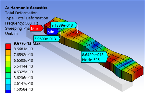
In addition to the result information displayed in the geometry window, the Results category in the Details pane displays the minimum, maximum, and average values for the given result, as well as the part names where the minimum and maximum values occur.

Go to a section topic:
Applying Results
To apply a result, you highlight the Solution object and select a result, result probe, or result tool from the options on the Solution Context Tab. You can also right-click the Solution object, select , and then choose from the result options. Once inserted into the Outline, you need to scope your result objects to geometric or meshing entities of the model.
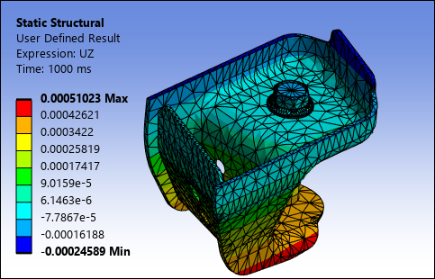
Note: See the User Defined Result section of the Help for more information about the specification and definition of this result type.
Assumptions and Limitations
Note the following when evaluating results:
When using the Mechanical APDL solver, the default solver, the Mechanical post processor caches the result and nodal (X, Y, Z) data in single precision format (rather than double precision) in order to conserve memory. This processing requirement can affect accuracy. For an analysis with high precision requirements, the implication can be significant. Note the following comparison of Displacement result values for the Mechanical APDL "MAPDL" application versus the Mechanical application.
UX UY UZ MAPDL POST1 Displacement Values 0.487107183574E-004 0.758421247657E-004 0.103875499252E-003 Mechanical Displacements Values 4.871071724e-005 7.58421229e-005 1.038754999e-004 If you suppress any result object, the application clears all generated data.
Because of software limitations, Mechanical currently cannot display the results of some types of nodes and elements. For example, a total deformation display in Mechanical excludes the deformations of nodes that are not attached to elements (like nodes associated with remote points).
Mechanical requires the mesh information to be present on the Mechanical APDL result file in order to postprocess. Therefore, result files created from Mechanical APDL cannot have the /CONFIG,NORSTGM option set to 1 (the default is zero).
Common Results Options and Features
Examine, interpolate, and display results of your simulation using the various features.
| Option/Feature | Description/Example |
|---|---|
|
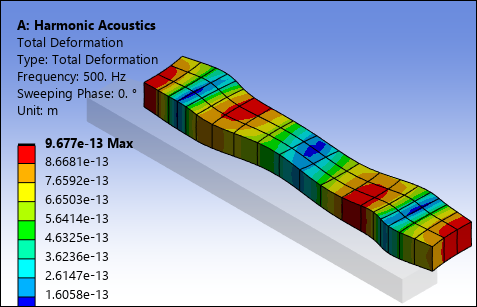
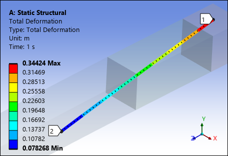
Contours |
Display result contours of solution quantities such as displacement, stress, temperature, electric field density, etc., over the entire model or a selected portion (part/body) of it.
|
|
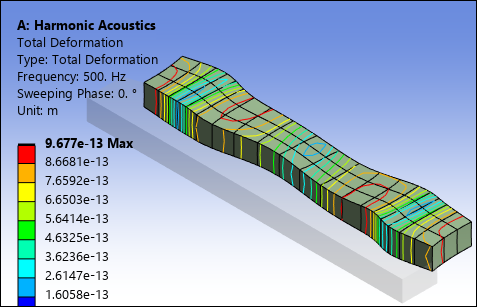
Use display options to quantify and visualize result contours, including vectors, iso-surfaces, slice planes, path operations, surface cuts, and capped iso-surfaces.
| |
|
Create probes to calculate abstract engineering quantities such as reaction forces, reaction moments, and virtual strain gauges.
| |
|
Create customized results using the User Defined Result object.
| |
|
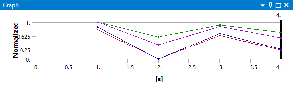
Chart minimum and maximum values over time for multiple result sets.
| |
|
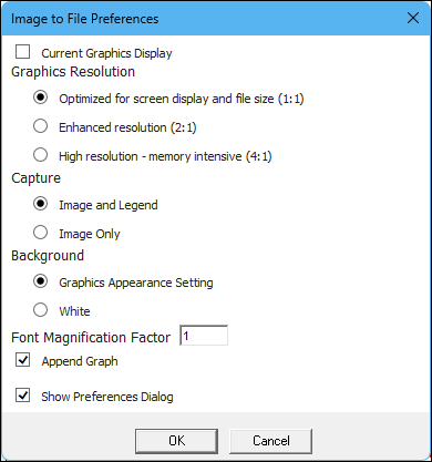
Export result data in a variety of formats, such as ASCII files for raw data, static images such as *.png, *.avi animations, as well as HTML reports.
| |
|
Interpolate results to investigate values at a location where no nodes exist. For example, a path result consists of arbitrary (non-node-based) locations.
|