


This feature enables you to take base excitations or load vectors created by an upstream Modal analysis or imported from an Imported Condensed Part object and apply and scale them to a downstream Harmonic Response Mode Superposition (MSUP) analysis.
This page includes the following topics:
| Analysis Types |
| Dimensional Types |
| Geometry Types |
| Magnitude Options |
| Applying a Load Application Boundary Condition |
| Automatically Defined Load Application Objects |
| Details Pane Properties |
Analysis Types
The Load Application feature is supported during the following analysis:
Note: If you activate Beta Options, and specify the feature option Load vector generation in Modal analysis ( > Options > > ), this feature is also supported by a Transient Structural Analysis Using Linked Modal Analysis System.
Dimensional Types
The supported dimensional types this boundary condition include:
3D Simulation
2D Simulation
Geometry Types
Not applicable to this feature.
Magnitude Options
Magnitude values are included in the source data. You use the properties of this object to scale the source data. The Magnitude properties of the downstream analysis that scale the load data, as described below, support and entries.
Application
This procedure assumes that you have properly prepared the simulation to the point where you can now insert the Load Application object into a Harmonic Response MSUP analysis. That is, you have properly imported your condensed parts with load vectors or configured and solved your Modal or pre-stressed Modal analysis and inserted the desired MSUP analysis.
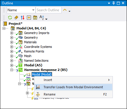
Tip: When you have a Modal analysis linked to a downstream system, you can use the initial specification object to automatically generate Load Application objects. The Harmonic Response analysis includes a Modal initial specification object. Right-click the object and select . The application automatically creates one Load Application object for each base excitation or load with Program Controlled Load Vector Assignment defined in the upstream system as well as one Load Application object for each load vector number assigned to upstream loads for Manual Controlled Load Vector Assignment. See below for additional information.
To specify a Load Application object:
Right-click the environment object of the MSUP harmonic system and select Insert > Load Application.
Specify the Scoping Method property as either , , or . Based on your selection, specify one of the following additional properties:
Source: Select a desired modal load or Imported Condensed Part from the drop-down list. When you set the Scoping Method to property to , this property displays the default option . This setting instructs the application to scale all of the load vectors of all available Imported Condensed Part objects.
Load Vector Number: Enter the desired load vector number. The value is the same as the load vector number specified in the associated upstream load object or the selected imported condensed part. When you set the Source property to a specific Imported Condensed Part object, this property displays the default option (
0). This setting instructs the application to scale all of the load vectors included in the Imported Condensed Part. You can also manually enter a desired . These values are shown in the Worksheet for the Imported Condensed Part object.
Specify the Absolute Result property for base excitation source loads. Options include Yes (default) and No. Set this property to No if you do not want to include enforced motion.
Important: If you apply more than one base excitation, the Absolute Result property for each must have the same setting, either Yes or No.
Define the Magnitude property. Magnitude properties for scaling displacement base excitations have a length unit and scaling acceleration base excitations have acceleration unit. They are otherwise unitless.
Automatically Defined Load Application Objects
The application examines each upstream base excitation and load to determine how to define the properties of the associated downstream Load Application object. Note the following:
For an upstream base excitation, the application automatically sets the Type property of the downstream Load Application object to .
For an upstream loading condition whose Load Vector Assignment property is set to , the application automatically sets the Scoping Method property of the downstream Load Application object to .
For an upstream loading condition whose Load Vector Assignment property is set to , the application automatically sets the Scoping Method property of the downstream Load Application objects to and then assigns the associated load vector numbers to the objects.
Important: If more than one of the loading conditions uses the same load vector number, the application only creates one Load Application object for that particular load vector number, not multiple objects.
Object Reference - Details Pane Properties
The Details pane for Load Application object includes the following properties.
| Category | Property/Options/Description |
|---|---|
|
Scope |
Scope Mode: Read-only property that describes whether the object is created manually or using the content (right-click) menu option of the initial specification object (described above under the Tip). Scoping Method: This property specifies whether the Load Application object scales an upstream Modal base excitation or load, load components with the same load vector number, or Imported Condensed Part load vectors. Options include (default), , or (if applicable). Source: Visible when the Scoping Method is set to or . This property provides a drop-down list of valid modal loads included in the upstream Modal analysis or available objects. Valid loads include base excitations and loads with Load Vector Assignment property set to . Load Vector Number: Visible when the
Scoping Method is set to or .
Enter the desired load vector number. The value is the same as the load vector
number specified in the associated upstream load object or the selected imported
condensed part. When you set the Source property to a
specific Imported Condensed Part object, this property
displays the default option
( |
|
Definition |
Type: Read-only field that describes whether the upstream Source load generated a base excitation or load vectors when Scoping Method is . Absolute Result: For Base Excitation Type only. This option enables you to include enforced motion with or without base motion. Options include (default) and . Magnitude: This property defines the scaling of the upstream Imported Condensed Part load vectors or the upstream Modal analysis loads.
Suppressed: Exclude the object in the analysis. Options include (default) and . |
|
Step Controls (Multiple Step Harmonic Response Analyses Only) |
Step Varying: Options include No (default) and Yes. When you select No, the Load Application object is applicable at all defined steps. When set to Yes, only the load step selected in either the RPM Selection or Step Selection properties described below is applicable. RPM Selection: This property displays when the Multiple Step Type property is set to RPM. Select an RPM Selection value from the drop-down menu. Step Selection: This property displays when the Multiple Step Type property of the Analysis Settings object is set to Load Step. Specify a Step Selection value from the values available in the Load Step Value property of the Analysis Settings object to use for the Load Application object. |