


Use the connections Worksheet to supplement the use of the Details pane by providing a summary of the contact information, joint information, and the connections between geometry bodies.
Go to a section topic:
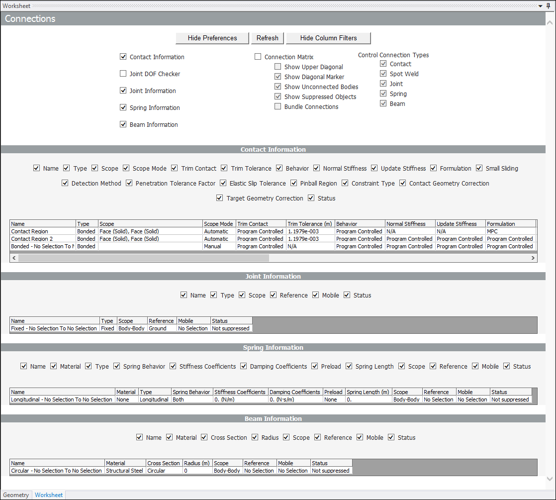
Worksheet Display
to display the connections Worksheet:
Select the Connections folder and then select Worksheet option from the Connections Context tab. The worksheet displays and includes the and options.
Select the option. The available data types display.
Select the check boxes for the data types you want to view.
Select the option. The application remembers the display preferences you select and they will become the default for future sessions.
Once you generate worksheet content, the Hide Column Filters button displays along with the filters pertinent to the available connections data. Select this option to hide the filters as desired. Once selected, the button label changes to Show Column Filters. These buttons toggle the display of the filters on and off. You can also use the check boxes of each individual filter and show/hide the associated column in the worksheet. You can also use the context (right-click) menu to turn the filter options on and off when you place the cursor over/in the table data.
Navigation
Once selected, the Worksheet remains displayed as you select different objects within the Connections folder. When you select an object outside of the Connections folder, the application displays your model. When you return to the worksheet display, you need to again show the preferences and generate connection data.
Worksheet Connections Data Types
The following data types are available in the worksheet. When you activate or deactivate these option, you need to select the Refresh button to display the data.
- Contact Information
Displays the properties for each contact region.
- Joint DOF Checker
Checks the total number of free degrees of freedom and displays the free DOF, based on the number of unsuppressed parts, fixed constraints, and translation joints. If this number is less than 1, the model may be overconstrained, and you should check the model closely and remove any redundant joint constraints. You can use a Redundancy Analysis to detect redundant joint constraints.
- Joint Information
Displays the name, type, scope, and status of all joints.
- Spring Information
Displays spring connection properties.
- Beam Information
Displays beam connection properties.
- Connection Matrix
Displays a matrix that represents the connections between bodies in the geometry. These connections are color-coded by type (as shown in the legend). In the Preferences, you can choose the type of data to display, in order to filter out unwanted information. Activate the options by checking the selection box beside the Connection Matrix title. The following options can then be selected or deselected as desired.
The option is an especially useful tool because it enables you to group Control Connection Types. For example, if you have three Spot Welds contained in the same cell of the matrix, activating the option displays the spot welds as "3 Spot Welds" instead of displaying the individual names of all three within the cell.
Note:The matrix displays a grounded connection as a connection to itself. For example, if a grounded joint is scoped to body1, then it will be displayed in the cell of column body1 and row body1.
The Connection Matrix is limited to 200 prototypes.
- Control Connection Types
The Control Connection Types display area provides a list of selectable connection features/types that you can choose to display or to not display within the Connection Matrix. Options include:
Contact
Spot Weld
Joint
Spring
Beam
Context Menu Selection Options
Selecting an item in the table and then right-clicking the mouse provides a menu of the following options, in addition to those associated with the properties of the data types:
: the application displays the associated contact object or objects in the Geometry Window.
: if you change the order of the table content by clicking on a column title, this option resets the order of the table content.
: reset the columns to the default width.
: changes column width (in pixels). You can select multiple columns or rows. A value of zero (default) indicates that the setting is program controlled.
(Connection Matrix Only - see below)
Exporting the Connection Matrix
You can export a text file version of the Connection Matrix from either the Worksheet or the Connections object in the Outline.
To export from the worksheet, right-click the Connection Matrix table and select .
To export from the Outline, right-click the Connections object and select .