


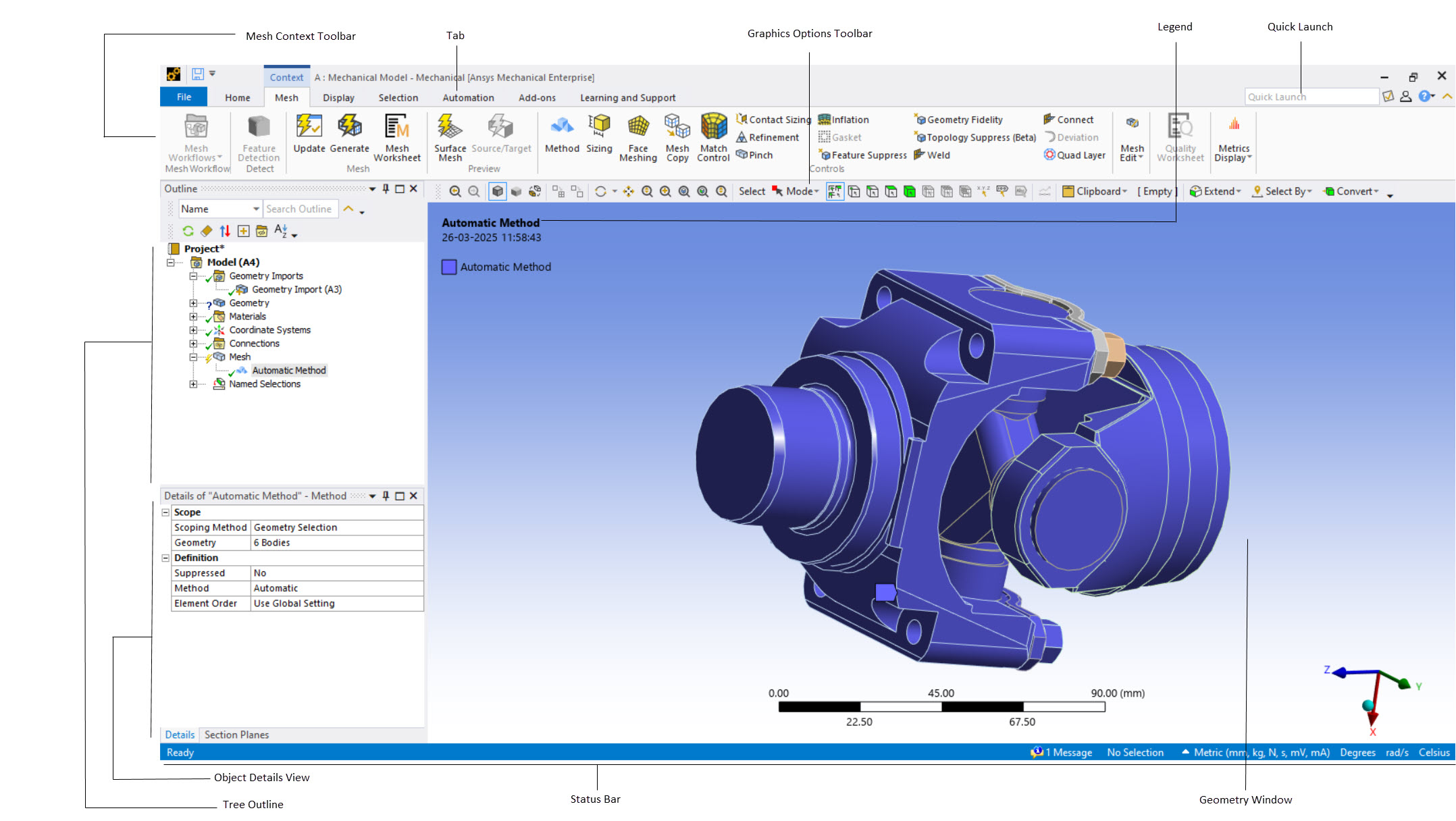
The intuitive Meshing application interface, which is shown in Figure 3: Meshing Application Interface, facilitates your use of all meshing controls and settings.
The functional elements of the interface are described in the following table.
Note: The links in the table redirect you to topics in the Ansys Mechanical help that contain supplemental information. Not all of the items described in the Mechanical help are available in the Meshing application interface.
| Window Component | Description |
|---|---|
| Tab | This menu includes the basic menus such as and . |
| Graphics Toolbar | This toolbar contains commands that control pointer mode or cause an action in the graphics browser. |
| Context Options Toolbar | This toolbar contains task-specific commands that change depending on where you are in the Tree Outline. |
| Tree Outline | Outline view of the project. Always visible. Location in the outline sets the context for other controls. Provides access to object's context menus. Allows renaming of objects. Establishes what details display in the Details View. |
| Details View | The Details View corresponds to the Outline selection. Displays a details window on the lower left panel which contains details about each object in the Outline. |
| Geometry Window (also sometimes called the Graphics window) |
Displays and manipulates the visual representation of the object selected in the Outline. This window may display:
Note:
|
| Reference Help | Opens an objects reference help page for the highlighted object. These are the same pages that are available in the Mechanical application. |
| Quick Lauch | The document tabs that are visible on the lower right portion of the window. |
| Status Bar | Brief in-context tip. Selection feedback. |
| Splitter Bar | Application window has up to 3 splitter bars. |