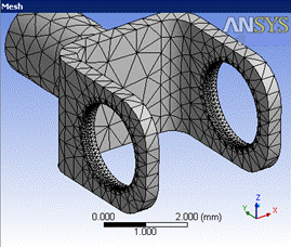
Arbitrary Match Control allows you select multiple pairs of faces or edges in a model to create a match control that consequently generates exactly the same mesh on the high geometry as it does on the low geometry. You can select a set of high faces belonging to different parts, and low faces belonging to different parts, provide that the high and low pairs are on the same body. For example, you can have a single match control consisting of multiple pairs of faces or edges across bodies.
Cyclic match controls requires you to select a coordinate system with its z-axis of rotation aligned to the geometry's axis of rotation but, for arbitrary match controls the faces or edges to be matched can be arbitrarily located, and the match control is based on two coordinate systems that you select.
You can scope an Arbitrary Match Control to either a geometry selection or a named selection.
If you want to automatically generate solver constraints for periodic mesh in addition to matching the mesh, you should use the Symmetry feature in the Mechanical application.
To access the Match Control control,
On the Tree Outline, right-click Mesh and click Insert > Match Control.
Or
On the Tree Outline, click Mesh and click Match Control in the Mesh Context tab on the Ribbon.
Right-click on the face or edge in the Geometry window and then select Insert > Match Control.
Scope
Scoping Method: Allows you to scope the geometry selections or named selections. The default value is Geometry Selection.
Geometry Selection: Allows you to scope the geometry faces. When you select Geometry Selection, the available options are:
High Geometry: Allows you to select the first faces or edges for the Match Control.
Low Geometry: Allows you to select the second faces or edges in the Match Control
Named Selection: Allows you to scope the bodies grouped under a named selection. When you select Named Selection the available option are:
High Boundary: Allows you to select the named selection for the Match Control.
Low Boundary: Allows you to select the named selection or edges in the Match Control.
Definition
Suppressed: Allows you to suppress the method control. The default value is No. When is set to Yes, the Active provides the number of suppressed parts and is read-only.
Transformation: Allows you to select the transformation type of match control. The default value is Cyclic. When set to Arbitrary, the available options are:
High Coordinate System: Choose the coordinate system for the faces or /edges assigned by the High Geometry Selection control.
Low Coordinate System: Choose the coordinate system for the faces or /edges assigned by the Low Geometry Selection control.
Axis of Rotation: Defines the rotation for the match control axis.
Control Messages: Provides an error message when mesh fails. You can click Control Messages to view the message.
Note: All the coordinate systems currently defined for the model appear in the High Coordinate System and Low Coordinate System drop-down menus. You may choose coordinate systems from the list, or you may need to define additional coordinate systems. For the match control to be honored, the coordinate systems that you choose must be defined such that a valid transformation matrix can be calculated. Else, the two coordinate systems must be created such that when the coordinates of every point of the Low Geometry Selection in the Low Coordinate System are placed into the High Coordinate System, the high and low faces/edges match exactly. Refer to the Coordinate Systems Overview in the Mechanical help for information on coordinate systems and how to create them.
Example 5: Arbitrary Mesh Matching
The figures below show an example of arbitrary mesh matching. Figure 113: Coordinate Systems for Arbitrary Mesh Matching shows the selected coordinate systems, and Figure 114: Matched Mesh shows the resulting matched mesh. Edge and face sizings were also applied.


