


This tutorial includes:
This tutorial demonstrates the basic workflow for generating a CFD mesh for a shrouded centrifugal compressor using Ansys BladeEditor and Ansys TurboGrid. Part of the shroud is attached to the blades. An axisymmetric shroud cavity separates the stationary parts of the shroud from the rotating part. As you work through this tutorial, you will use BladeEditor to outline a cross section of the shroud cavity on an axial-radial plane. You will then use TurboGrid to produce a mesh that includes a secondary flow path. The resulting mesh is usable by Ansys CFX in a CFD simulation.
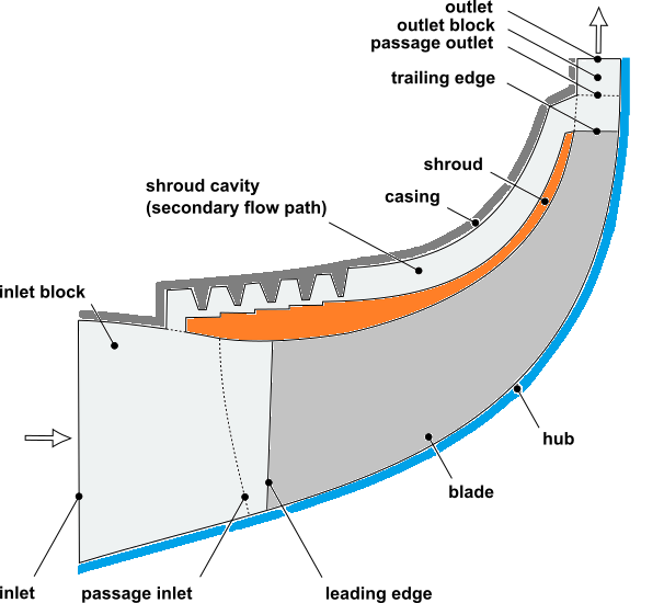
A schematic diagram of the case is shown below.
Note: This tutorial shows how to interactively set up a secondary flow path. It is possible to automate this process by importing an NDF file. For details, see Specifying Secondary Flow Paths By Importing NDF Files in the TurboGrid User's Guide.
If this is the first tutorial you are working with, it is important to review Introduction to the Ansys TurboGrid Tutorials before beginning.
Create a working directory.
Ansys TurboGrid uses a working directory as the default location for loading and saving files for a particular session or project.
Download the
secondary_path.zipfile here .Unzip
secondary_path.zipto your working directory.Ensure that the following tutorial input file is in your working directory:
shrouded impeller with cavity.wbpz
Alternatively, if you want to run TurboGrid in stand-alone mode (without having to run DesignModeler/BladeEditor), the following files are needed:
secondarypath_turbogrid.tginit
secondarypath_turbogrid.x_b
If running in stand-alone mode:
Launch TurboGrid.
Load the .tginit file.
You can expect a message stating "Geometry filepath was not specified". Click OK to dismiss it.
Continue this tutorial from Associating CAD Objects with Topology in TurboGrid’s Geometry Workspace.
In the following sections, you will load an Ansys Workbench project file that contains the Ansys BladeEditor geometry, then in Ansys BladeEditor, you will define line bodies and curve groups that will be used by TurboGrid in creating a mesh.
Start Ansys Workbench.
To launch Ansys Workbench on Windows, click the Start menu, then select All Programs > Ansys 2025 R2 > Workbench 2025 R2.
To launch Ansys Workbench on Linux, open a command line interface, type the path to
runwb2(for example,~/ansys_inc/v252/Framework/bin/Linux64/runwb2), then press Enter.
From the main menu, select File > Open.
The Open dialog box appears.
Browse to the working directory, set File name to
shrouded impeller with cavity.wbpz, and click Open.The Save As dialog box appears.
Accept the default name and click .
The true secondary flow path has an axisymmetric geometry. In this section, you will use BladeEditor to create a 2D closed loop, consisting of line bodies, that outlines the secondary flow path on an axial-radial plane. A 2D sketch of the secondary flow path is provided with the project just opened.
A secondary flow path can have one or more interfaces to the shroud or hub. In this tutorial, there are two interfaces to the shroud. In order to define any given interface to the shroud, the outline must not simply run closely along the shroud curve for the extent of the interface. Instead, to avoid an ill definition (sensitive to numerical round-off) of the interface location, the outline is required to cross the shroud curve into the main passage at one end of the interface, then cross back over the shroud curve at the other end of the interface. For meshing purposes, the outline will be, in effect, trimmed by the shroud curve. For an interface of a secondary flow path to the hub, a similar requirement applies.
A Geometry system is visible in the Project Schematic view.
Right-click the Geometry cell, and select Edit Geometry in DesignModeler... to launch DesignModeler.
Note: The BladeModeler Licensing preference is set to "No" by default. Before using BladeEditor, set the licensing preference to "If Available" or "Yes". The licensing preference is in DesignModeler: Tools > Options > DesignModeler > Addins > BladeModeler > BladeModeler Licensing. After changing the licensing preference, close then re-open DesignModeler.
You are now ready to edit the geometry using BladeEditor (which is accessed via DesignModeler).
In DesignModeler, select Concept > Lines From Sketches.
The details view shows the properties for a new line object. The Base Objects property is ready to be defined.
In the tree view, select
A:Shrouded Impeller>MerPlane1>S1_ShroudCavity.In the details view, beside Base Objects, click Apply.
Property Base Objects is now set to 1 Sketch. The selected sketch, S1_ShroudCavity, will appear in the tree view under the line object after you generate the latter.
Click Generate.
Select Tools > Attribute.
The details view shows the properties for a new attribute object.
Set Attribute Feature Name to
ImpellerShroudGroup.Set Attribute Name to
NamedSelection:ImpellerShroud2D.Note that the prefix "NamedSelection:" is required.
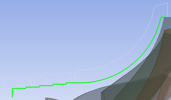
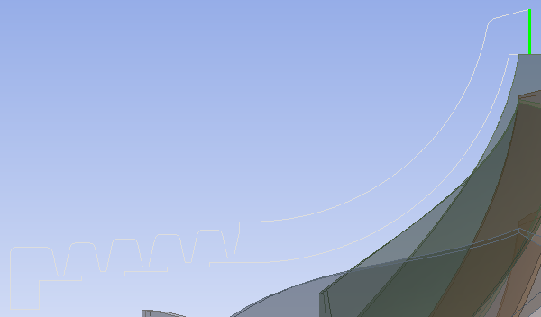
For property Geometry, select all 12 of the curves (edges) of the sketch for the secondary passage (S1_ShroudCavity) that are between the shroud interfaces and that are on the main passage side of the cavity, as shown below.
Start by clicking the field, beside property Geometry, that currently states "None (Document Level Attribute)".
The field will change into two buttons: Apply and Cancel.
Click Single Select
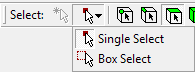 to start preparing for the selection of curves from the viewer.
Click the selection filter for edges
 to finish preparing for the selection of curves from the viewer.
Click a curve in the viewer, then, while holding Ctrl, click each of the other 11 curves to add them to the selection.
With the appropriate curves selected for property Geometry, click Apply, then click Generate.
Create three other attribute objects as follows:
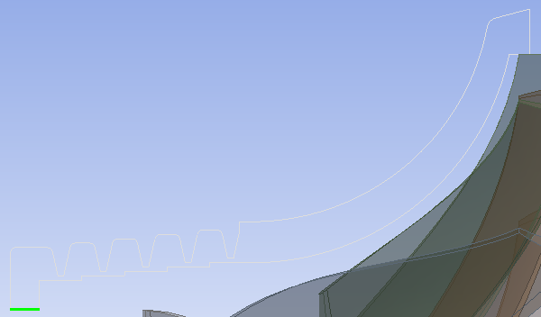
Attribute Feature Name=InterfaceLEGroup; Attribute Name=NamedSelection:InterfaceLE2D; Geometry=curve shown
Attribute Feature Name=InterfaceTEGroup; Attribute Name=NamedSelection:InterfaceTE2D; Geometry=curve shown
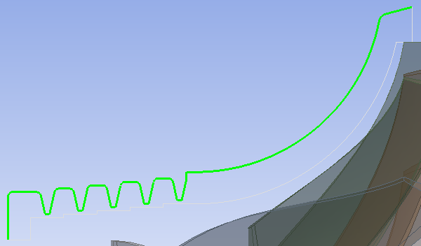
Attribute Feature Name=CasingGroup; Attribute Name=NamedSelection:Casing2D; Geometry=36 curves shown
Right-click the Geometry cell, and select Transfer Data To New > TurboGrid.
A new TurboGrid system appears with a link from the upstream Geometry system.
Right-click the Turbo Mesh cell, and select Edit to launch TurboGrid.
Before a mesh can be generated in TurboGrid, the geometry must be defined as per the following sections:
In TurboGrid, click the Geometry tab to switch to the Geometry workspace.
In the object selector, right-click Topological Entity Instances > Secondary Flow Paths and select Insert Secondary Passage.
The Create New Secondary Passage Topology dialog box appears.
Set Name to
Shroud Cavityand click OK.Incomplete secondary flow path object
Shroud Cavityappears in the tree underSecondary Flow Paths. This object requires boundary entity definitions. In this case, you will add four boundary entity definitions: one for each of the two interfaces with the shroud, and one for each side of the cavity (casing side and shroud side).Right-click
CAD Families>CASING2Dand select Create Entity and Assign Family > Shroud Cavity.The Create New Secondary Passage Boundary dialog box appears.
Accept the default name (
CASING2D1) and click OK.Boundary entity
CASING2D1is listed in the tree underShroud Cavity. Incomplete secondary flow path objectShroud Cavityindicates an error (via red text) because it does not currently represent a closed loop.Using the same technique as for the previous two steps, create three other boundary entities under
Shroud Cavity:IMPELLERSHROUD2D1,INTERFACELE2D1,INTERFACETE2D1.For example, create boundary entity
IMPELLERSHROUD2D1using CAD FamilyIMPELLERSHROUD2D.When you are finished this step, secondary flow path object
Shroud Cavitywill represent a closed loop and will no longer indicate an error.
Set the type for each of the four boundaries of the shroud cavity:
In TurboGrid, click the Mesh tab to switch to the Mesh workspace.
In the object selector, under
Geometry>Secondary Flow Paths>Shroud Cavity:Open
CASING2D1and ensure that its Boundary Type is set toWall.Open
IMPELLERSHROUD2D1and ensure that its Boundary Type is set toWall.Open
INTERFACELE2D1, set its Boundary Type toShroud Interfaceand click Apply.Open
INTERFACETE2D1, set its Boundary Type toShroud Interfaceand click Apply.
Switch to the axial-radial view so that you can better see the location of the cavity with respect to the main passage:
In the upper-left corner of the 3D Viewer, select View 3, then click Fit View
 .
.
The inlet and outlet blocks should preferably contain the interfaces to the cavity:
This is the case for the inlet block, which contains
INTERFACELE2D1. As a result, the shroud can be (and will be, later in this tutorial) automatically divided into regions that align with the edges ofINTERFACELE2D1. Such alignment helps to improve mesh quality near the interface.This is not the case for the outlet block, which fails to contain
INTERFACETE2D1. In this case, the upstream edge ofINTERFACETE2D1is already aligned with the topology in the main passage (the cut-off trailing edge). In order to create topological alignment between the other edge ofINTERFACETE2D1and the topology in the main passage, you will next move the passage outlet to that edge.
Move the passage outlet as follows:
Open
Geometry>Outlet.Select Interface Specification Method > Points.
Select
Low Hub Point, then set Method toSet Rand Location to0.054.Click Apply.
Select
Low Shroud Point, then set Method toSet Rand Location to0.054.Click Apply.
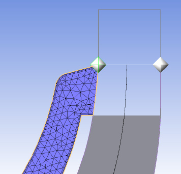
The passage outlet should now be located as shown by Figure 7.1: Passage Outlet at Downstream Edge of Shroud Cavity.
This completes the geometry definition.
The Topology Set object is initially suspended in order to save
computational effort while defining the geometry. When you unsuspend the
Topology Set object, the remaining computations are performed,
resulting in a 3D mesh.
Make changes to the Topology Set, Layers,
and Mesh Data objects as follows:
Open
Topology Set.Select Split Mesh Regions At Trailing Edge and click Apply.
This causes the shroud region in the main passage to be subdivided so that the cavity can be joined downstream of the cut-off trailing edge to a mesh region called "SHROUD DOWNSTREAM".
Open
Layers.Set Insertion Mode to
Manual - Uniform.Set Count to
1.Click Apply.
Open
Mesh Data.On the Mesh Size tab, set Method > Size Factor to
1.3and Parameters > Factor Base to4.0.Ensure that Inlet Domain and Outlet Domain are selected.
Click Apply.
Next, generate the mesh:
Right-click
Topology Setand turn off Suspend Object Updates.The 3D mesh is generated. The number of nodes and elements are displayed at the bottom left.
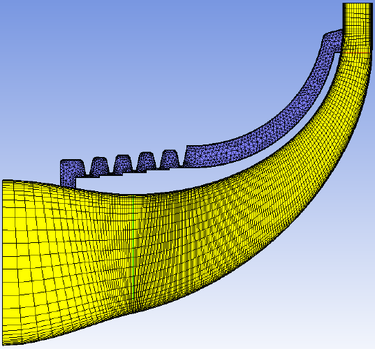
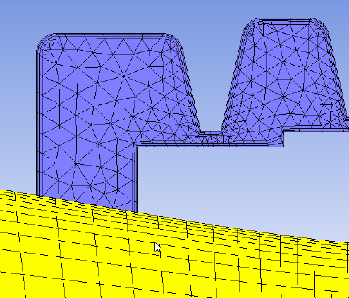
Figure 7.2: Meridional View of Mesh (with Blade LE and TE) shows the current mesh.
As shown in Figure 7.3: Upstream Shroud Cavity Interface with Inlet Block - Misaligned Topology, the cavity and main passage meshes are not topologically aligned at the edges of the interface.
Open
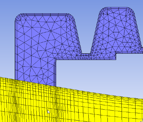
Geometry>Secondary Flow Paths>Shroud Cavity>INTERFACELE2D1.Select Automatically Manage Opening Region and click Apply.
A new shroud region,
AUTO INTERFACELE2D1, is generated and can be reviewed in theGeometry> Shroud object editor on the Shroud Regions tab.
As shown in Figure 7.4: Upstream Shroud Cavity Interface with Inlet Block - Aligned Topology, the cavity and main passage meshes are now topologically aligned at the edges of the interface.
The interface connecting regions are listed under 3D Mesh:
Leading edge interface regions:
AUTO INTERFACELE2D1
Shroud Cavity > Shroud Cavity INTERFACELE2D1
Trailing edge interface regions:
SHROUD DOWNSTREAM
Shroud Cavity > Shroud Cavity INTERFACETE2D1
Adjust the mesh for the secondary flow path as follows:
Open Mesh Data > Shroud Cavity.
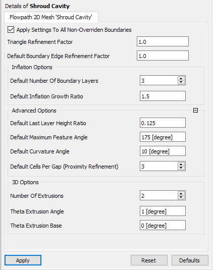
Increase the overall mesh refinement by increasing
Default Boundary Edge Refinement Factorto2.Increase boundary layer refinement and decrease the height of the first layer of elements along all shroud cavity boundaries by increasing Inflation Options > Default Number Of Boundary Layers to
6.You can review the height of the first layer of elements along a shroud cavity boundary by looking in the object editor for
Mesh Data>Shroud Cavity>[Boundary name].Decrease the boundary layer element growth rate by decreasing Inflation Options > Default Inflation Growth Ratio to
1.3.Increased refinement in the labyrinth seal tooth gaps by increasing Advanced Options > Default Cells Per Gap (Proximity Refinement) to
6.Click Apply.
The current design only requires a thin mesh. For cases that require a mesh that is thicker in the circumferential direction, 3D options are available.