


There are two primary ways to create a project in Sherlock:
As demonstrated in Tutorial: Ad Hoc Project Creation, you can add individual files to your project using the Add File(s) feature. The kinds of files Sherlock can process is extensive, including layer files, drill files, data files, Gerber files, pick and place files, bills of material, and so on. You will find a complete list of file-types in the next section Circuit Card Assembly Files.
Or, as described in this section, you can create a project by using the Import... feature to import an entire archive or project file from one of the industry-standard file types.
Whether you are in single or multi-project mode, you can import a project at any time by selecting one of the Import... options from the Project menu.

Table 3.3: Import-Compatible Project Files
|
Ansys EDB File ODB Archive IPC-2581 Archive |
CADIF Archive Eagle Archive ODB XML Archive |
GDSII File |
Topics Covered in This Section:
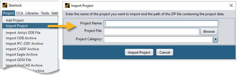
To import a Sherlock project, select Import Project from the Main Menu. This will open the Import Project dialog. Here you specify a Project Name and click the Browse button to select the project file. Project Category is an optional field. (You may change the Project Category later by right-clicking the project folder in the Project Tree and selecting Project Properties.) Finally, click Import Project.
Depending on the size of the project file, the import may take a minute or so to load. During that time, a progress dialog will be displayed. Once the import is complete, the project will appear in Sherlock's Project Tree. For additional details on importing a Sherlock project, refer to Importing a Project in the Tutorial: Project Overview.
As mentioned earlier, you can import a variety of industry-standard file types into Sherlock. Simply click Project from the Main Menu and select one of the Import... options. This will open the dialog for the specific file type you chose. The Import IPC-2581 dialog is shown below as an example of the import interface. Click the Browse button to navigate to the file you wish to import. Notice the top field (A, below) displays the file path. The second field (B) displays the file name.
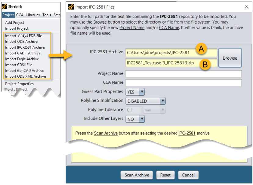
Other options in the Import Files dialog:
Project Name and CCA Name: (Optional) You can specify a Project Name and a CCA Name if you wish. If these fields are left blank, Sherlock will use the name of the imported file for the Project Name and CCA Name.
Guess Part Properties: When set to YES (default), Sherlock will attempt to guess certain part properties based on the part descriptions. When set to NO, Sherlock will not guess part properties. Except for Package Type, Model Part status, and Lead Modeling status, only properties specified in the file will be populated.
Polyline Simplification: (Disabled by default) When ENABLED, Sherlock simplifies the board outline by reducing the number of points which comprise the outline. This can resolve meshing issues that happen when too many vertices define an outline. See Polyline Tolerance below.
Tip: You can also perform Polyline Simplification after importing the file. Use the Edit Board Outline function in the Layer Viewer. See Board Outline Editor in the Layer Viewer Tutorial.
Polyline Tolerance: Sherlock uses this tolerance value for the Polyline Simplification feature. In the polygon outline, any point that is within the specified distance of another will be removed.
Include Other Layers: By default, Sherlock only imports layers it can use. When you set this option to YES, Sherlock will import any layer found in the archive. These additional layers will appear in the Other Layers folder of the Layer Viewer.
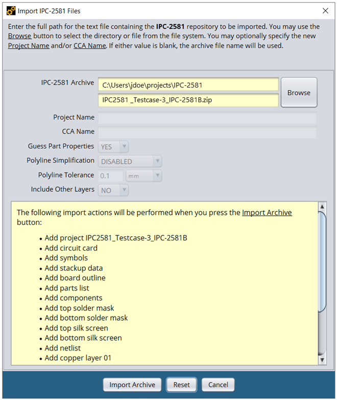
Once you have selected the file you wish to import, click the Scan Archive button. Sherlock will perform a preliminary scan of the selected file and display the list of import actions it will perform as shown below. To continue with the import, click the Import Archive button. If you do not wish to proceed with the import, you can click Reset. This will clear the file name and the results of the file scan so you can start over.
Each file type has its own import dialog with file-specific parameters. Special considerations for each file-type are contained in the sections that follow. For a detailed explanation of how to import a project, refer to these tutorials:
Tutorial: ODB++ Project Creation in the Getting Started chapter
The IPC-2581 Import Tutorial below
The following is a list of industry standard file types you can import into Sherlock. Each has its own import dialog with file-specific parameters. Special considerations for each file type are noted in the descriptions below.
Tip: See Importing Other File Types above for explanations of import options that apply to all file types.
- Ansys EDB File
(.def) Currently, the EDB import supports copper layers, laminates, board outline, and stackup data.
- ODB Archive
(.tgz, .tar.gz, .tar) A CAD to CAM data exchange file. Importing and working with an ODB++ archive is covered in detail in the Tutorial: ODB++ Project Creation.
Note: When importing a BGA package from an ODB++ archive, Sherlock calculates the package dimensions from the ball pattern rather than using the dimensions specified for the package. See The Importance of Reviewing Part Properties.
- IPC-2581
(.cvg, .xml, .zip) See the IPC-2581 Import Tutorial below for details.
- CADIF Archive
(.paf) CADIF files are generated from Zuken PCB layout software applications.
- Eagle Archive
(.zip, .tgz, .tar.gz, .tar) EAGLE (Easily Applicable Graphical Layout Editor) is a scriptable electronic design automation (EDA) application.
Note: When importing a BGA package from an Eagle archive, Sherlock calculates the package dimensions from the ball pattern rather than using the dimensions specified for the package. See The Importance of Reviewing Part Properties.
- GDSII File
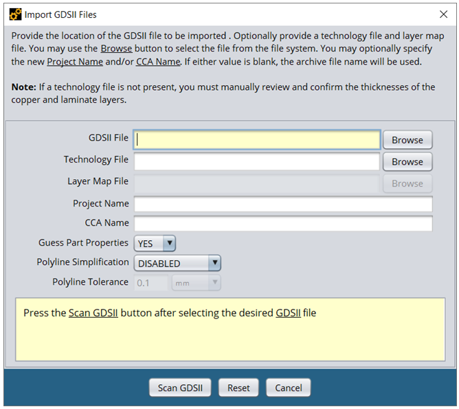
(.gds, .sf, .strm) GDSII is an industry standard database file format used for exchanging integrated circuit layout artwork. In Sherlock, the Import GDSII Files dialog, shown below, gives you the option to import a Technology File (.xml, .tech, .layermap) and a Layer Map File (.map). Click the check box to launch the project in ECAD Xplorer. Use the Project Directory field to specify the folder where you want to save the imported project.
Note: If a technology file is not present, you must manually review and confirm the thicknesses of the copper and laminate layers.
- ODB XML Archives
(.xml, .xml.gz, .xml.z, .gz, .z) Note: When importing a BGA package from an ODB XML archive, Sherlock calculates the package dimensions from the ball pattern rather than using the dimensions specified for the package. See The Importance of Reviewing Part Properties.
IPC-2581 is an open global standard for assembly and manufacturing data supported by the IPC-2581 Consortium. More information about IPC-2581 can be found at http://www.ipc2581.com. Sherlock supports IPC-2581 revision A and B of the standard for a FULL function mode IPC-2581 file (USERDEF mode in revision B). Some other function mode levels may produce results within Sherlock however these other modes typically do not include all the necessary data for Sherlock to completely define a circuit card. Some of the example files found on the IPC-2581 website are not FULL function mode examples.
A list of supported and known unsupported elements from IPC-2581 can be found at the end of this section.
For the purposes of this tutorial, Test Case 3 for revision B will be used from the IPC-2581 Consortium website. These sample files can be found at http://www.ipc2581.com/b-test-cases.
Note: If you download the test cases from the IPC-2581 Consortium website, be aware there is an issue with Test Case 6. The project defines a cutout which surrounds the PCB. This causes Sherlock to eliminate the board during FEA model generation. You should delete the cutout after importing the project.
In this section, the following topics are covered:
An IPC-2581 file is a text-based XML file containing the complete definition of the printed circuit card, such as the components, layers, BOM, etc. IPC-2581 files prior to revision B of the standard, end with a .cvg extension, and end with a .xml extension with revision B. Sherlock also supports having one of these files enclosed with a .zip file. If there is more than one matching file type found in the zip archive, only the first match will be processed. Note that some of the example files provided by the IPC-2581 Consortium are .zip files. However, these zip files also include ODB++ archives, and other formats and documentation used for comparison and reference to the contained IPC-2581 file. When using these files to import into Sherlock, the desired .cvg or .xml file should be first extracted from the archive to insure the correct IPC-2581 file is imported.
To import an IPC-2581 file, select the Import IPC-2581 Archive from the Project menu. This will display a dialog to allow the selection of the IPC-2581 file to be imported, along with additional options that allow for manual override of the project name and CCA name. By default, Sherlock will only bring in layers from the IPC-2581 file that Sherlock uses. The option Include Other Layers will tell Sherlock to bring in any layer found in the IPC-2581. These additional layers will appear in the Other Layers folder of the Layer Viewer.
After selecting the desired file to import and optionally changing any other options, click the Scan Archive button to begin the import process. The file will first be pre-processed, and a dialog named the Component Property Mapping dialog, like the following will be displayed:
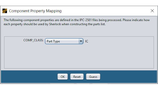
The Component Property Mapping dialog is an important, but sometimes overlooked, dialog that allows you to map various component/part properties included in the IPC-2581 file to corresponding Sherlock property fields. Sherlock parses any BomItem description and BomItem textual characteristics found in the IPC-2581 file to produce this dialog. The item COMP_CLASS in this example was found and the value IC was an example value found in the file. If desired, the indicated Sherlock part property will be assigned the values found for COMP_CLASS associated with each part found. If the indicated Sherlock part property is not correct or the indicated IPC-2581 property doesn't apply, change the selection to the correct Sherlock part property or to the value of Ignore.
Note: Starting with version 2023 R1, Sherlock's Component Property Mapping dialog now lists the NonstandardAttribute tag if it is found in the IPC-2581 file.
Note: In this example, only one property is defined and the names are easily matched with Sherlock property names. In a real-world archive, there can be dozens of property names, in which case you'll need to determine which, if any, should be mapped to Sherlock properties.
After you've reviewed the various properties and have decided that they are mapped appropriately, press the OK button to continue the import process.
After the part properties have been mapped the Import IPC-2581 Files dialog will display the complete list of data that can be extracted automatically from the archive, as shown here:
In this case, Sherlock has found a complete set of files, including package information, stackup data, board outline, drill holes and all the important layers. Additionally, because the Include Other Layers option was selected, it found five additional layers to import which are not used directly by Sherlock.
For ease of use and because of the larger size of IPC-2581 files, Sherlock will extract the XML that makes up each of the found items in the list of imported items above. Each will display as a separate XML file within Sherlock and properly associated to each layer within Sherlock.
Press the Import Archive button to start the import process, at which point the import dialog will close and the project navigation tree will be updated to include all the files being imported, as shown below. While each file is imported, the icon displayed next to the file will reflect a clock icon. Once complete, the appropriate file icon for the given file will be reflected. If any errors were generated while processing the files, then the file will be highlighted with an orange "?" icon.
At this point, the IPC-2581 file has been imported into Sherlock creating a new project containing a new circuit card. Project management can continue by reviewing part properties and various layers as detailed in Lesson 04 – Reviewing Part Properties and Lesson 05 – Layer Viewer of the Sherlock tutorial.

Many of the examples provided by the IPC-2581 Consortium also provide additional import types such as ODB++ for the examples to be used as a comparison. The ODB++ examples may also be loaded into Sherlock, see the ODB++ Project Creation tutorial more information. When doing so you might notice some discrepancies between an ODB++ version of a file and the IPC-2581 revision A and B versions of a file.
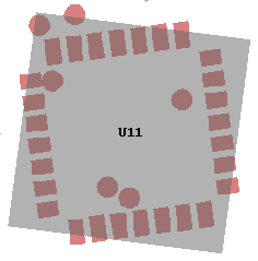
One such example appears with the test case 3 file used as an example in this user’s guide section. If you view the bottom component and solder mask layers in Sherlock you will notice that component U11 appears to be rotated differently than the soldermask layer, however in the ODB++ version of the same example, the rotation is correct.
IPC-2581defines rotation values as counter-clockwise as viewed from the top of the board. Mirroring is done across the Y-axis and is performed after rotation. If you right-click the comp.xml file in the Files section of the imported IPC-2581 file, you can select View File from the menu to see how this component is specified. Component U11 is found near the bottom of the file. As shown below, the component is rotated to the left or counter-clockwise 82.601 degrees, then mirrored across the Y-axis meaning that all X values are set to -X. Because component U11 is rotated incorrectly, the rotation may be fixed by changing the component rotation or mirror setting.
| <Component refDes="U11" packageRef="PLCC28" layerRef="BOTTOM" part="FILTERED" mountType="SMT" standoff="0.0" height="0.175"> |
| <Xform rotation="82.601" mirror="true"/> |
| <Location x="1.750" y="1.350"/> |
| </Component> |
For comparison, the same component from the ODB++ archive is defined with a rotation of 277.4 and no mirroring. Rotation values in ODB++ are performed clockwise.
| CMP 5 1.75 1.35 277.4 N U11 ??? ;0=1,1=0.175000 |
In the IPC-2581 specification, section 4.1 Content: FunctionMode shows a table of how various functions are supported between the different function modes and levels. Sherlock requires most items from revision A FULL mode or revision B USERDEF mode:
Table 3.4: IPC-2581 Element Requirements
| Name | Sherlock Supported |
| Hierarchical layer/stack instance files | Yes |
| Hierarchical conductor routing files | Yes |
| BOM | Yes |
| AVL | No |
| Component Packages | Yes |
| Land Patterns | No |
| Device Descriptions | Yes |
| Component Descriptions | Yes |
| Soldermask: Solder Paste Legend Layers | Yes |
| Drill and Routing Layers | Yes |
| Documentation Layers | Optional |
| Net List | Yes |
| Outer Copper Layers | Yes |
| Inner Layers | Yes |
| Miscellaneous Image Layers | Optional |
| DFX Analysis | No |
Sherlock supports most of the IPC-2581 specification, however there are some items which are not supported as Sherlock provides its own implementation for them or they are not required for use by Sherlock. The following tables indicate what is supported. This is not a meant to be a complete list but does cover most of the functionality that Sherlock normally provides.
Table 3.5: IPC-2581 Specification Support
| IPC-2581 Item and Section | Status | |
| 3.3 Transformation characteristics (Xform) | Supported | |
| 3.4 Substitution Groups | ||
| Not supported | |
| Supported | |
| lineProperty not supported; all lines are solid | |
| fillProperty of void and solid are supported | |
|
All shapes; Moire and Thermal are not fully supported | |
| Text attribute not supported | |
| 4. Content | ||
| Supported as StandardPrimitive above | |
| Supported as UserPrimitive above | |
| Not supported | |
| Supported as LineDescGroup above | |
| Supported as FillDescGroup above | |
| Not supported | |
| Not supported | |
| 7. BOM | ||
| Supported | |
| 8. ECAD | ||
| Supported | |
| ||
|
Supported; DrillTool not supported | |
| Supported | |
| ||
| Supported | |
| Not supported | |
| Fiducial, SlotCavity, ColorGroup not supported | |
Other Limitations When Importing IPC-2581 Files
Test points are created from component TP reference designators, not testPoint definitions.
All arcs (other than circles and corners of rounded rectangles) are discretized into small lines when IPC-2581 files are imported into Sherlock.