


The Sherlock Solder Manager allows for a user to create and modify Sherlock solder definitions. Properties modified in the Solder Manager are used during analysis. The Solder Manager is accessible by selecting Libraries > Solders from the Sherlock menu and is also a standalone utility accessible from the Sherlock start menu folder.
In this section, the following topics are covered:
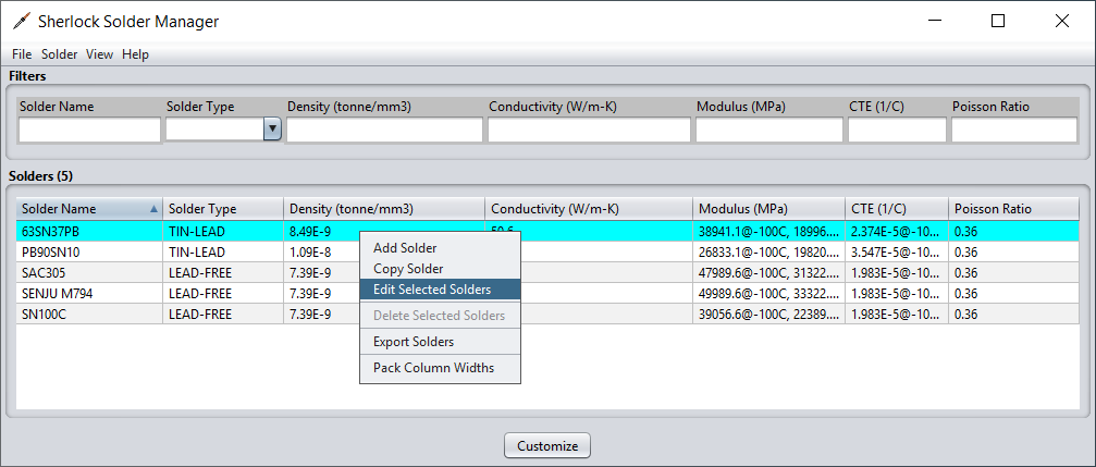
The main Solder Manager window is organized into two sections. The top section provides a set of fields to allow filtering of the solders in the manager. The bottom table is a list of all solders or those solder matching any selected filters from above.

To filter the solder definitions to only the TIN-LEAD solder types, enter or select TIN-LEAD in the Solder Type column filter and press Enter. This will immediately filter the solder table to only display solders that at TIN-LEAD. Multiple filters may be applied. The table is filtered when all applied filter definitions match a given solder.
This main window for the Solder Manager can be customized and filtered in ways similar to the customization and filtering detailed in the Parts List Management users guide. The actions include, selecting the visible columns and advanced filtering techniques. Refer to the Parts List Management users guide for details on using these features.
To view or edit a given solder, you may double-click the desired solder from the solder table listing. You may also right-click the solder in the solder table listing and select Edit Selected Solders from the context menu.
After selecting a solder to edit, the Solder Editor dialog window will be displayed. This window provides a look at all the property values defined for the selected solder and allows for those property values to be modified.
After selecting a solder to edit a new dialog window will appear with a listing of all the available material properties for the selected solder. From the Solder Editor a user can view and make changes to any of the material properties. The Solder Editor Groups properties into different categories, represented by tabs in the editor.
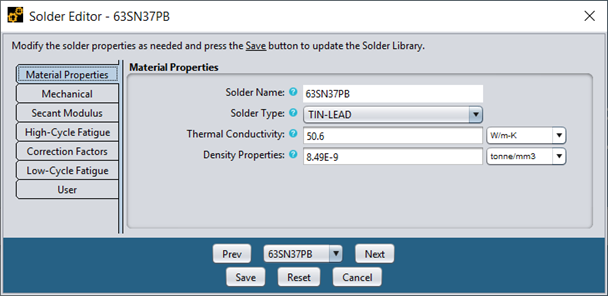
For properties which indicate a unit of measure, the currently selected unit of measure for that property is displayed next to the field. By selecting a new unit of measure from the list, the value displayed in the form will automatically be converted to the selected units. These includes fields which may have specified multiple temperature-dependent properties.
The User tab provides a place to specify notes about a given solder and indicate the creator of the solder and also user that last modified the solder. If a solder does not have any customized values, then the Created By and Modified By fields will be listed as Ansys, Inc.
After making any desired solder changes, use the Save button to save the changes to the local copy of the Sherlock Solder Library. See the section User Data Files for more information about the location and format of the local Solder Library. If you don't wish to save any changes or are simply viewing the solder definition, select the Cancel button when done. The Reset button will revert any changes you have made to the definition since opening the dialog to the original settings.
Note: If you modify any of the solders provided by Sherlock, future Sherlock updates to the solders will not be reflected until the customized solder is removed.
If you wish to view additional solder definitions, you may do so without closing the solder editor dialog window by simply selecting the solder from the selector at the bottom of the window or using the Prev and Next buttons. The solder selector and the Prev and Next buttons are both limited to the filtered solders from the solder manager itself. If no filters were applied, then the entire list of solders is available.
Temperature-dependent values can be specified for the following properties:
Elastic Modulus (MPa)
Poisson Ratio
CTE (1/C)
Density Properties (tonne/mm3)
Thermal Conductivity (W/m-K)
Fatigue Exponent, Fatigue Coefficient, FEA Power, Critical Strain, and Shock Strain (used for shock and vibration fatigue cycles to failure calculations)
Temperature-dependent values are defined as a set of temperature-value pairs and are passed directly to the FEA engine for all materials used during a given analysis. FEA engines typically use the given data points to determine the property value for a specific temperature by using linear interpolation between the bounding data points. For all temperatures below the minimum temperature specified, the value associated with the minimum temperature will be used. Similarly, for all temperatures above the maximum temperature specified.
Temperature-value pairs are specified using the following notation:
| <Value> @ <Temp> <Units> |
where <Value> is the property value, <Temp> is the temperature and <Units> are the temperature units. (NOTE: The value units must be those specified in the list above.) Two or more temperature-value pairs must be comma separated. For example, the following notation:
| 400@20C, 320.5@212F |
specifies a value of 400 at 20 degrees centigrade and a value of 320.5 at 212 degrees Fahrenheit. Temperature units can be freely mixed in a given list of temperature-value pairs.
In situations where Sherlock needs to determine a temperature-dependent material property value when no explicit temperature is defined (such as when mixing material property values in a given PCB layer to determine the average layer property value), a room temperature value of 20C is used for interpolation purposes.
To assist with computing temperature dependent values for the CTE and Elastic Modulus properties, Sherlock provides a temperature value calculator for these properties. This calculator takes in a base CTE or Elastic Modulus value, a Tg value, temperature range, and inputs that control the number of temperature values to produce to provide a set of temperature dependent values.
From the Solder Editor for the solder 63SN37PB, select the Mechanical tab to reveal the current CTE and Elastic Modulus values.
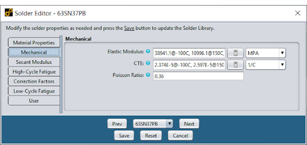
The default solder contains several CTE and Elastic Modulus values. To use the calculator to expand this list, click the calculator icon button next to the desired field.
When you click the calculator for Elastic Modulus, the Temperature-Dependent Properties Calculator launches. As shown below, the calculator provides a set of default input properties used to compute additional material temperature values for the selected property. The default Tg and Modulus < Tg (or CTE values) originate from the source material. Note the default values shown below: The Number of Points is 10 which means the calculator will generate ten material temperature values for elasticity within the range of -60° and 140° Celsius. Because the calculator generates additional temperature values at the Max and Min Temperatures, the total number of values generated will be twelve.

Upon clicking the Compute button, the values will be computed, and the underlying field updated with new material temperature values. To accept these values, click the Save button for the solder and they will be committed.
Note: The default values of any system provided solder can be restored by using the Delete Selected Solders menu item from the Solder Manager listing. Deleting system provided solders simply resets those material property values.
To add a new solder, select Add Solder from the Solder menu, or right-click in the solder table listing and select Add Solder from the menu. The solder editor dialog will appear with all material properties empty, ready for a new solder to be defined. When you are complete defining a solder, click the Save button to add the new solder.
To copy a solder, right-click the solder to be copied from the solder table listing and select Copy Solder from the menu. A copy of the solder will be made. Provide a solder name for the copied solder and make any changes desired to the material properties, then click the Save button to add the copied solder.
Any user-defined solder that is not a Sherlock system solder may be deleted. Right-click the solder to be deleted from the solder table listing and select Delete Solder from the menu. If the Delete Solder item is not available, this indicates that it is not a user-defined solder.
If a system solder has been modified, the Delete Selected Solders menu item will be available. However, it will not actually delete the solder. Deleting a system solder that has user-defined properties will simply remove all the user-defined properties and allow the solder to revert to being completely system defined.
Solder definitions may be exported to CSV or XLS spreadsheet files to allow external viewing or modifications. Exported files can then be used to import solder definitions back into the solder manager.
To export all Solder Definitions, select from the File menu Export Solders or right-click in the solder table listing and select Export Solders from the context menu. If you wish to export only specific solders, select the solders you wish to export from the solder table listing, then right-click the table and select Export Solders. In either case, the Export Solder Library dialog will be displayed.

The Rows and Columns selections allow you to customize which rows and/or columns should be exported. Select All Rows if all rows should be exported or select Selected Rows if only the rows selected in the solder table listing should be exported. Similarly, select All Columns if all columns should be exported or select only specific columns to be exported.
After specifying the output file location, click the Export button. Supported file extensions are .csv, .xls, and .xlsx. If successful, a message will appear indicating the number of rows selected.
Solder definitions may be imported into the Solder Manager from a CSV, XLS or XLSX spreadsheet file by selecting the File > Import Solders option from the main menu. At that point, a file dialog will be displayed allowing you to designate the file to be imported.

After selecting the file, the Import Solder File dialog will appear, allowing you to verify the column mapping for each file/sheet that is imported. Sherlock scans each file in an attempt to determine the number of header rows, the column names and which columns should be mapped to the various Sherlock solder properties. Such guesses are usually right, but you should check them anyway by viewing the import file using an appropriate spreadsheet application.
When the import form is filled out properly, press the Import Solders button to import the data.
When the import process has completed, you will see a confirmation dialog. If any solder definitions fail to import, then none of the rows in the file will be imported and an error dialog will be displayed with the information regarding why a particular solder definition failed to be imported.