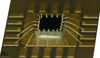
Wire bonding is a common method used to connect an integrated circuit to the pins or pads of the package in which it is contained. It is also used in some situations to make connections between a pair of ICs or between an IC and the PCB. In either case, the wires used are usually made of aluminum, copper, silver or gold. Wire diameters can be as small as 15 microns or as large as several hundred microns for high-powered applications.
Ansys Sherlock allows users to interactively define one or more wire bonds that attach to either a component or the PCB at designated locations. Users can also import/export batches of wire bond definitions via various file formats.
Note: When wire bonds are enabled for FE analysis, the corresponding analysis results for mechanical shock, vibration, and ICT will each include a results table for each wire bond.
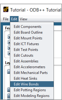
Wire bonds are added using the Edit > Edit Wire Bonds menu option found in the 2D Layer Viewer main menu, accessible by double clicking Layers under Inputs in the Project Tree. When selected, the Wire Bond Editor control buttons will be displayed at the bottom of the 2D Layer Viewer panel and the Mechanical > Wire Bonds layer category will be enabled so that all existing wire bonds will be displayed. Wire bonds are displayed as thin dark yellow lines by default. You can change the display color assigned to wire bonds using the Settings > General Settings > Color menu option available in the Sherlock main menu.
To add a wire bond, right-click anywhere on the circuit card and select the Add Wire Bond option from the context menu. At that point, the Add Wire Bond dialog will be displayed, allowing you to specify the desired properties for the new wire bond. Sherlock automatically assigns a unique ID to each wire bond, but you are free to change the ID to whatever is required, provided it is still unique.
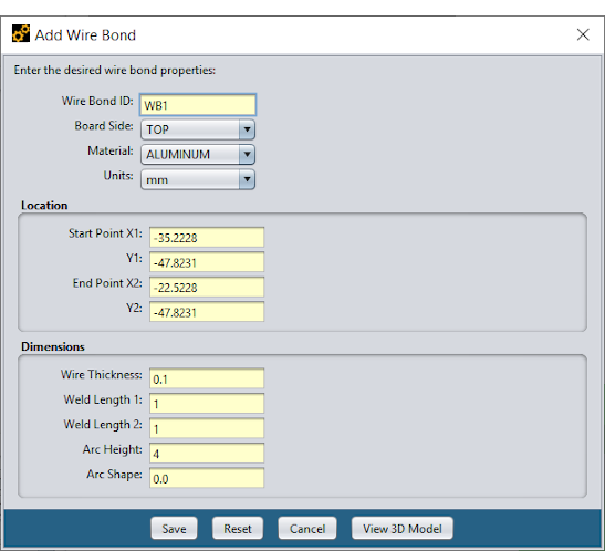
The Board Side property specifies the side of the board on which the wire bond is located. Sherlock will automatically determine which component(s), if any, are located under the wire bond whenever a 3D model is generated. This allows users to freely position wire bonds and components without having to maintain correlations between them.
The Material property specifies the type of material used for the wire bond, which is passed directly into the resulting 3D FEA model.
The Location panel defines the start and end points of the wire bond. Such locations are typically edited graphically in the layer viewer (more on this shortly), but you are free to enter exact locations in the dialog as well.
The Dimensions panel defines the relevant dimensions (illustrated below) of the wire bond. The Wire Thickness property defines the square cross section of the wire.
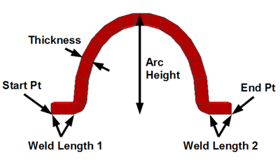
The Weld Length properties define the length of the foot on each end of the wire where it is connected to the underlying component or PCB.
The Arc Height property defines the height of the arc, measured from the HIGHEST foot position. For example, if the start point of the wire bond is sitting on top of a component and the end point is sitting on the PCB, then the Arc Height will be measured from the top of the component, not the PCB surface.
The Arc Shape property controls the shape of the Bezier curve generated by Sherlock to represent the wire as it bends from the start point to the end point (which may have different vertical coordinates), through the specified height. Bezier curves are well-suited for 3D modeling, because they are smooth enough to prevent any distortions, yet they can be controlled by a single property.
The Arc Shape property is specified as a numeric value between 0 and 1 that defines how pointy the arc will be, as depicted in the following images.
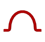
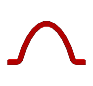
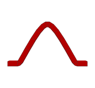
An Arc Shape value of 0.0 results in a very full arc, that comes up almost vertically from each foot and has a wide, rounded form. An Arc Shape of 1.0 results in a narrow, almost triangular arc.
The View 3D Model button at the bottom of the wire bond property dialog can be used to visualize the impact of the various dimensional properties on the wire bond arc. Once pressed, the Wire Bond Viewer will be displayed, showing the 3D model for the current set of properties, assuming that each foot of the wire bond is sitting at the same vertical level.
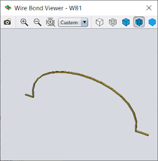
As with other 3D viewers in Sherlock, you can pan, zoom and rotate the model as needed to examine the shape. You can also generate a snapshot image for documentation or reporting purposes.
If you change any of the property values in the property dialog, simply press the View 3D Model button again to update the 3D display using the new properties.
Existing wire bonds can be edited graphically in the 2D Layer Viewer or using the Edit Wire Bond dialog. In both cases, the editing process begins by left-clicking a wire bond in the 2D Layer Viewer while holding down the SHIFT key to select the wire bond. Once selected, the wire bond will be highlighted by a red polygon with 6 control nodes, as shown in this image.
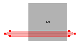
To change the location of either end point, simply left-click any of the control nodes and drag them to the desired location. The normal pan and zoom features provided by the 2D Layer Viewer can be used at any time to more precisely position the wire bond end points as needed. To change the location of the wire bond without changing its overall length, left-click anywhere inside of the highlighted region and drag the entire wire bond to the desired location.
You can right-click anywhere in the selected wire bond region to display the following additional editing options:
Edit Properties
Copy Wire Bond
Delete Wire Bond
The Edit Properties menu option displays the Edit Wire Bond dialog that is identical to the Add Wire Bond dialog previously discussed. The Edit Wire Bond dialog allows you to modify any of the properties associated with the wire bond.
The Copy Wire Bond menu option immediately copies the selected wire bond to a nearby location and selects the new wire bond for editing. Typically, the wire bond is then dragged to the proper location and the process is repeated for all the wire bonds needed by a given component. In this way, users can quickly define a set of identical wire bonds that vary only in their location.
The Delete Wire Bond menu option is used to delete an existing wire bond.
As with most other Sherlock 2D Layer editors, multiple wire bonds can be selected by SHIFT-left-clicking on the circuit card and dragging a rectangle around the desired wire bonds. Individual wire bonds can then be added to or removed from the selected set using SHIFT-left-click. With multiple wire bonds selected, the Copy Wire Bonds and Delete Wire Bonds context menu options can be used to copy or delete all of the wire bonds in the selected set.
In addition to the manual / graphical process discussed above, a batch of wire bond definitions can be imported from or exported to a spreadsheet or CSV file. This can significantly reduce the time required for data input in situations where the wire bond locations are known. The combination of the export and import capabilities can also be used to facilitate bulk editing needs, such as changing the material property for all wire bonds or just a subset.
All of the currently defined wire bonds can be exported to a spreadsheet or CSV file by selecting the CCA > Export Wire Bonds option from the Sherlock main menu. At that point, the Export Wire Bonds dialog (belowf) will be displayed, allowing you to specify the name, type and location of the file to be exported.
The following file formats are supported:
Excel Spreadsheet (*.xls)
Excel Spreadsheet XML (*.xlsx)
Comma Separated Value (*.csv)
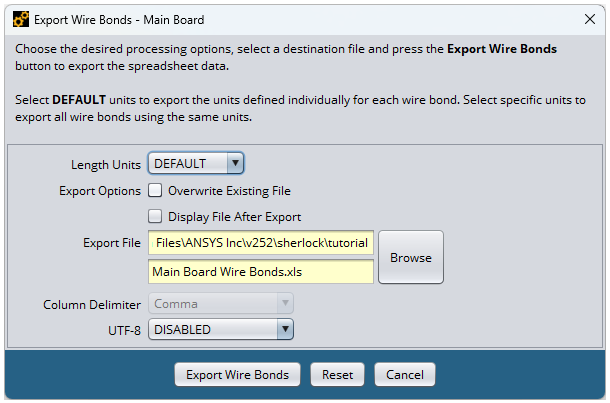
The Length Units property allows you to specify the units to be used for all wire bond properties, regardless of the units used in Sherlock to define those properties.
The Overwrite Existing File option indicates that any existing file with the same name should be overridden without further prompting.
The Display File After Export option specifies that the Windows application associated with the selected file format should be launched right after the file has been exported.
Wire bond definitions are imported by adding a spreadsheet or CSV data file to the CCA and assigning one of the following file types to that file:
Wire Bond (Excel)
Wire Bond (CSV)
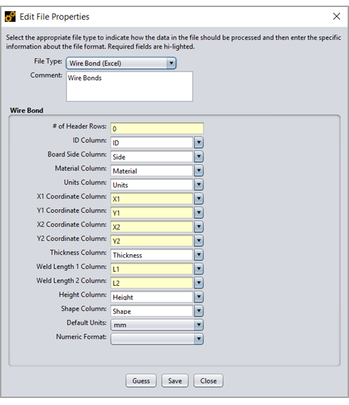
To add a file to the CCA, either select CCA > Add Files from the main Sherlock menu, or right click Files and select Add File(s) from the Project Tree. To assign a file type, open the File Properties editor (below) by right clicking the file, selecting Edit Properties, and then toggling the File Type drop down. With either file type assigned, a set of file parsing properties can then be used to designate the columns containing the desired data. Each column must begin with a text value containing the column name. Based on the column names, Sherlock will automatically attempt to match the appropriate column in the spreadsheet or CSV file with each wire bond property. Nonetheless, you are free to enter or select the proper column name for each wire bond property.
Once all of the required column names have been specified, press the Save button to parse the wire bond definitions and import them into Sherlock.
Note: All wire bond definitions found in the file will be added to any existing set of wire bonds. If you want to overwrite the existing wire bonds, you should delete all the existing wire bonds in the 2D Layer Viewer before importing from the file.
Wire bonds can be selectively enabled or disabled in the 3D FEA models created by each of the following operations:
Generate 3D Model
FE analysis
Export FEA Model
In each case, the Wire Bonds tab (below) is used to specify the desired wire bond modeling properties.
When enabled, 3D models are created for each wire bond. Each wire bond foot is bonded to the underlying component or PCB elements, depending on the location of the wire bond and Part Modeling properties.
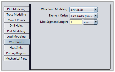
The Element Order property specifies the type of element to be used in the FEA tool for the wire bond. First Order elements are bricks specified by 8 nodes, while Second Order elements are bricks specified by 20 nodes.
The Max Segment Length property specifies the maximum linear distance covered by each arc segment. A shorter length results in a smoother arc, but also increases the number of elements created for each arc, which increases analysis time.
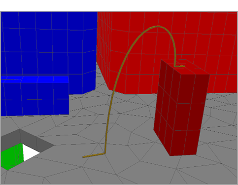
Sherlock automatically determines the proper Bezier arc for each wire bond based on the wire bond properties and the underlying component or PCB surfaces. As shown below, the arc will smoothly transition from one end point, through the maximum height, to the other end point. Proper specification of the foot length, thickness, arc height and arc shape properties allow for a wide range of different wire bonds to be effectively modeled.
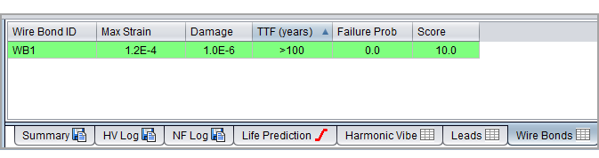
When wire bonds are enabled for FE analysis, the corresponding analysis results for mechanical shock, vibration, ICT, and thermal mechanical will each include a results table for each wire bond. For vibration analysis, users may select one or more wire bonds and right-click to view the life prediction chart for the selected wire bonds.