


The analysis of relative position, velocity, and acceleration between two coordinate systems is crucial for understanding the dynamic behavior of interconnected components within a multibody system. This process involves defining Base and Action markers, which represent the objects being analyzed, and a Reference Marker, utilized for coordinate transformations. The Reference Marker enables the comparison of physical quantities across different coordinate systems. For instance, in the analysis of vehicle dynamics, it is vital to measure the movement of components such as tires and seats relative to the vehicle's coordinate system. In this context, the vehicle's coordinate system acts as both the base and the reference system, while the coordinate systems of the parts serve as action markers. Such an approach allows for the precise calculation of component movements relative to the vehicle's frame, which is essential for optimizing design and performance.
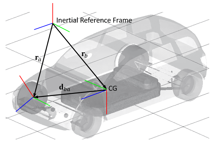
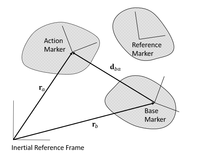
Relative displacement is the vector distance between corresponding points in two different coordinate systems. Specifically, the relative displacement between action and base markers with respect to the inertial reference frame is:
 | (2–65) |
where:
| ra = the position vectors of the action marker |
| rb = the position vectors of the base marker |
The relative displacement between markers with respect to the reference marker is:
 | (2–66) |
where:
Ar = the orientation of the reference marker
The magnitude and each component of the relative position vector are:
 | (2–67) |
 | (2–68) |
 | (2–69) |
 | (2–70) |
where:
 | (2–71) |
 | (2–72) |
 | (2–73) |
Relative orientation describes the rotational relationship between two coordinate systems. Specifically, the relative orientation of the markers with respect to the inertial reference frame is:
 | (2–74) |
where:
| Aa = the orientation of the action marker |
| Ab = the orientation of the base marker |
The relative orientation between markers with respect to the reference marker is:
 | (2–75) |
where:
| Ar = the orientation of the reference marker |
Relative angle refers to the angle measured between two coordinate systems. The relative angle can be represented using Euler angles and the projected angle derived from the relative orientation matrix. Motion supports two types of Euler angles: the ZXZ Euler angles (PSI-THETA-PHI) and the ZYX Euler angles (YAW-PITCH-ROLL), to measure relative angle between markers.
ZXZ Euler Angles
 | (2–76) |
 | (2–77) |
 | (2–78) |
ZYX Euler Angles
 | (2–79) |
 | (2–80) |
 | (2–81) |
Projected Angles
Projected angles are used to calculate the accumulated rotation angles, which are calculated as:
 | (2–82) |
 | (2–83) |
 | (2–84) |
where:
| N = the number of complete rotations. |
In Equation 2–82 to Equation 2–84, the accumulated angle is defined as the rotation angle accumulated over time between two markers. The objective of the algorithm is to accurately calculate the accumulated angle θa, taking into account the magnitude of relative rotational angles that may occur beyond the range of 0 to 2π during the time integration process. The motion solver assumes that the step size is sufficiently small that it does not rotate more than π in a step.
Steps to Calculate Accumulated Angle
Acquire the Relative Angle: Obtain the relative angle θ between two markers.
Initialize or Update the Previous Accumulated Angle: When starting, set the previous accumulated angle θ(a,prev) to zero. For subsequent calculations, update θ(a,prev) to the last calculated value of θa.
Calculate the Number of Complete Rotations: Determine the number of complete rotations that have been previously accumulated by using the floor function:

(2–85)
Generate Candidates for the New Accumulated Angle: Set three candidates for the new accumulated angle to account for the uncertainty in rotation direction (clockwise or counterclockwise).

(2–86)

(2–87)

(2–88)
Select the Minimum Deviation Candidate: Identify the candidate angle that is closest to the previously accumulated angle, minimizing the absolute deviation. This is done by finding the index imin where:

(2–89)
The resulting index corresponds to the candidate with minimal change from the previous accumulated angle, therefore ensuring continuity in the angle measurement.
Update the Accumulated Angle: Set the accumulated angle, θa, to the candidate angle corresponding to i_min.

(2–90)
This updated angle θa now becomes θ(a,prev) for the next iteration of the algorithm.
Accumulated angle is utilized in various entities, as shown in Figure 2.18: Entities Using the Accumulated Angle. When solver computes the accumulated angle, if the rotation in a single step exceeds π (Pi), the direction of rotation may be misinterpreted as the opposite of the actual direction. To ensure precise calculations of the accumulated angle, it is critical that the maximum step size hmax does not exceed:
 | (2–91) |
where:
| ωji = relative angular velocity between the two markers to be measured |
This situation primarily occurs when the body rotates at extremely high speeds. If a problem arises, the solver outputs a warning message in the .msg file.
Figure 2.18: Entities Using the Accumulated Angle
| Classification | Entity |
| Constraints | Coupler with revolute joint |
| Gear | |
| Rack and Pinion | |
| Screw Joint | |
| Constraints | |
| Revolute Joint | |
| Forces | Rotational Spring |
| Sub-entities | AX, AY and AZ in Function Expression |
| AX, AY and AZ in SYSFNC of User Subroutine | |
| RDISP in SYSARY of User Subroutine |
The relative translational velocity between markers, referred to the inertial reference frame, can be calculated by differentiating the displacement vector dba with respect to time. This yields:
 | (2–92) |
where:
 = the translation velocities of the action
marker = the translation velocities of the action
marker |
 = the translation velocities of the base
marker = the translation velocities of the base
marker |
The relative translational velocity between markers with respect to the reference marker is:
 | (2–93) |
where:
 = the orientation of the reference marker = the orientation of the reference marker |
The magnitude and each component of the relative translational velocity are calculated as follows:
(2–94) |
(2–95) |
(2–96) |
(2–97) |
where:
(2–98) |
(2–99) |
(2–100) |
The relative velocity in the direction of the relative displacement between the two markers can be defined as follows:
 | (2–101) |
The relative angular acceleration between markers, referred to the inertial reference frame, can be calculated by differentiating the relative angular velocity wba with respect to time. This yields:
 | (2–102) |
where:
| wa = the angular velocity of the action marker |
| wb = the angular velocity of the base marker |
The relative angular velocity between markers with respect to the reference marker is:
 | (2–103) |
where:
| Ar = the orientation of the reference marker |
The magnitude and each component of the relative angular velocity are calculated as follows:
 | (2–104) |
 | (2–105) |
 | (2–106) |
 | (2–107) |
where:
(2–108) |
(2–109) |
(2–110) |
The relative translational acceleration between markers, referred to the
inertial reference frame, can be calculated by differentiating the translational
velocity  with respect to time. This yields:
 | (2–111) |
where:
 = the translational acceleration of the action
marker = the translational acceleration of the action
marker |
 = the translational acceleration of the base
marker = the translational acceleration of the base
marker |
The relative translational acceleration between markers with respect to the reference marker is:
 | (2–112) |
where:
| is the
orientation of the reference marker |
The magnitude and each component of the relative translational acceleration are calculated as follows:
 | (2–113) |
 | (2–114) |
 | (2–115) |
 | (2–116) |
where:
(2–117) |
(2–118) |
(2–119) |
The relative angular acceleration between markers, referred to the inertial reference frame, can be calculated by differentiating the relative angular velocity wba with respect to time. This yields:
 | (2–120) |
where:
 = the angular acceleration of the action
marker = the angular acceleration of the action
marker |
 = the angular acceleration of the base
marker = the angular acceleration of the base
marker |
The relative angular acceleration between markers with respect to the reference marker is:
 | (2–121) |
where:
| is
the orientation of the reference marker |
The magnitude and each component of the relative angular acceleration are calculated as follows:
 | (2–122) |
 | (2–123) |
 | (2–124) |
 | (2–125) |
where:
(2–126) |
(2–127) |
(2–128) |