


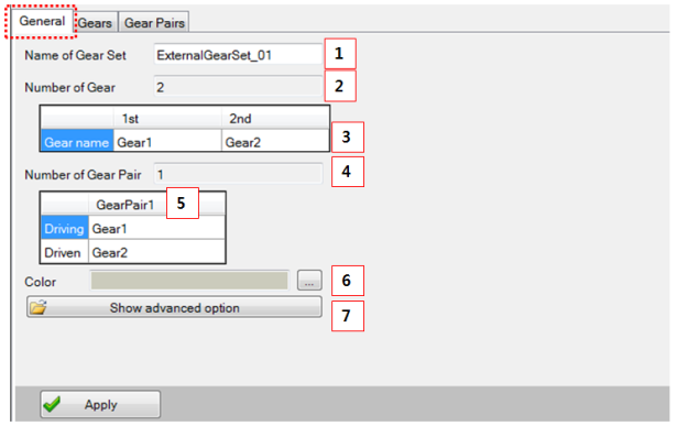
Figure 14.127: Parameters in the Gear set designer General tab
| Parameter | Description | Dimension |
| 1. Name | Use to set the gear set name. | N/A |
| 2. Number of Gear Set | Show the number gear. |
N/A (Integer>1) |
| 3. Gear Name | Use to set each gear name. | N/A |
| 4. Number of Gear Pair | Show the number of gear pair. | N/A (Integer>1) |
| 5. Color | Use to set the gear color. | N/A |
| 6. Show advanced option | Use to set the advanced option. | N/A |
The advanced options for the gear set are supported in the Advanced Option tab.
External, Internal (involute), Planetary, Worm & worm wheel, Cross Helical
Figure 14.128: Advanced Option tabs for External and Internal gear set (left) and Single Pinion Planetary gear set (right)
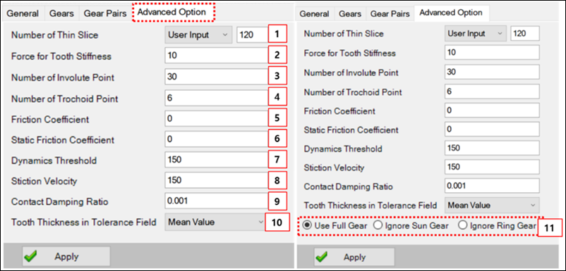
Figure 14.129: Parameters in the External gear set advanced options tab
| Parameter | Description | Dimension |
| 1. Number of thin slice |
Use to set the number of thin slice. The default value is that. - Spur : 30 - Helical : 120 | N/A (Integer>1) |
| 2. Force for Tooth Stiffness | Use to set the force for the calculating tooth stiffness. This value must be changed by the material and size of the gear. | Force |
| 3. Number of involute point | Use to set the number of involute point. This value is relate to the resolution of involute curve. | N/A (Integer>10) |
| 4. Number of trochoid point | Use to set the number of trochoid points. This value is related to the resolution of trochoid curve. | N/A (Integer>3) |
| 5. Friction coefficient | Use to set the friction coefficient. | N/A (Double>0.0) |
| 6. Static friction coefficient | Use to set the static friction coefficient. | N/A (Double>0.0) |
| 7. Dynamics threshold | Use to set the dynamics threshold. |
Length/Time (Real≥0.0) |
| 8. Stiction velocity | Use to set the stiction velocity. |
Length/Time (Real≥0.0) |
| 9. Contact damping ratio | Use to set the contact damping ratio. | N/A |
| 10. Tooth Thickness in Tolerance Field | Use to set the tooth thickness in the tolerance field. In the Tolerance tab for the gear, it is possible to select and use , , and for the minimum/maximum value of the generating profile shift coefficient for the tolerance item. The default setting is . | N/A |
| 11. Planetary Gearset Assembly Type |
Use to set the planetary gearset assembly type (only used for a planetary gearset). When configuring a gear combination for a planetary gear by user selection, the Sun or Ring gear can be excluded from the assembly.
The default type is Use Full Gear. | N/A |
Rack & Pinion
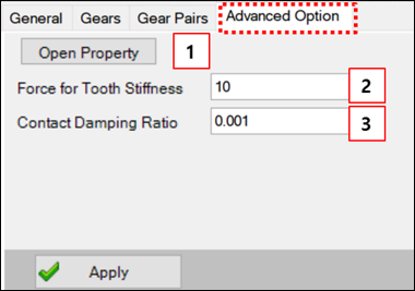
Figure 14.131: Parameters in the Rack and Pinion gear set Advanced Option tab
| Parameter | Description | Dimension |
| 1. Open Property |
Click to set the contact parameters. The parameters are same with "General contact". | N/A |
| 2. Force for Tooth Stiffness | Use to set the force for the calculating tooth stiffness. This value must be changed by the material and size of the gear. | Force |
| 3. Contact Damping Ratio | Use to set the damping ratio relative to tooth stiffness. |
N/A (Double > 0.0) |
Internal (Cycloid), Custom, Double Pinion Planetary
Figure 14.132: Advanced options for Internal (Cycloid), Custom and Double Pinion Planetary gear sets
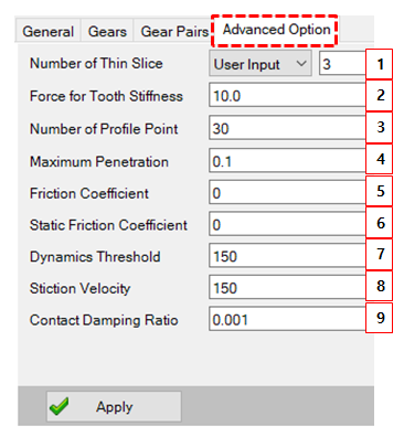
Figure 14.133: Parameters in the Internal (Cycloid) and Custom gear set Advanced Option tab
| Parameter | Description | Dimension |
| 1. Number of thin slice |
Use to set the number of thin slice. The default value is that. - Spur : 30 - Helical : 120 | N/A (Integer>1) |
| 2. Force for Tooth Stiffness | Use to set the force for the calculating tooth stiffness. This value must be changed by the material and size of the gear. | Force |
| 3. Number of profile point | Determine how many points are represent a cycloid shape. | N/A |
| 4. Maximum penetration |
Determine maximum penetration. More detailed explanation is explained in Maximum Penetration. | Length |
| 5. Friction coefficient | Use to set the friction coefficient. | N/A (Double>0.0) |
| 6. Static friction coefficient | Use to set the static friction coefficient. | N/A (Double>0.0) |
| 7. Dynamics threshold | Use to set the dynamics threshold. |
Length/Time (Real≥0.0) |
| 8. Stiction velocity | Use to set the stiction velocity. |
Length/Time (Real≥0.0) |
| 9. Contact damping ratio | Use to set the contact damping ratio. | N/A |