


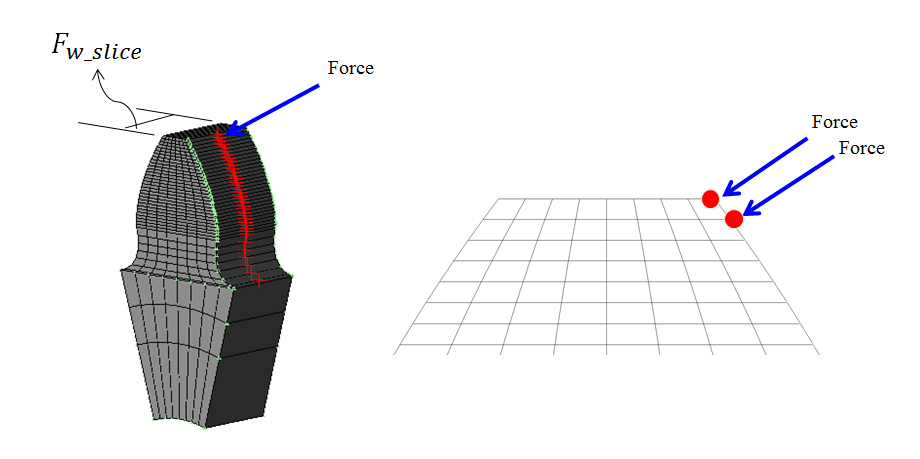
The tooth stiffness is a necessary parameter for the gear set. It can be calculated by using FE method. The gear root is fixed and the force is applied on the surface node. And then the deformation of the node is measured.
 | (14–27) |
where,  is the face width of
gear,
is the face width of
gear,  is the number of thin
slice. The tooth stiffness
is the number of thin
slice. The tooth stiffness  is calculated as follows.
 | (14–28) |
where, F is the apply force which is defined in the advanced option,  is a deformation of each node.
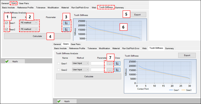
Figure 14.181: Parameters in the Tooth Stiffness tab
| Parameter | Description |
| 1. Select Gear | Check the gear to calculate the stiffness. |
| 2. Method | Select the calculation method of tooth stiffness. |
| 3. Draw | Select the gear to display the tooth stiffness. |
| 4. Calculate | Run the Motion/Solver to calculate the tooth stiffness. |
| 5. Export | Tooth stiffness export to *.text or *.csv file. |
| 6. Tooth stiffness Graph | Show the each tooth stiffness. |
| 7. Parameter | Use to use the property files for simulation scenario. |
From 2022 R1 version, this function has been changed to perform automatically. The conditions for automatic tooth stiffness calculation are as follows.
1. When user select the method as FE method and user do not perform the tooth stiffness calculation.
2. When user select the method as FE method and some parameters are changed.
Figure 14.182: Conditions to calculate tooth stiffness automatically
| Tab | Sub-tab or Parameter |
| 1. Gears | Basic Involute |
| Tool | |
| Tolerance | |
| Modification | |
| Material | |
| 2. Advanced Option | Number of Thin Slice |
| Force for Tooth Stiffness | |
| Number of Involute Point | |
| Number of Trochoid Point |