


A Nodal FE body is created by importing an FE data file in a mesh. The FE data file can be generated using a Beam FE Body or the other mesh generation software. NASTRAN, Workbench 11.0 and user-defined FE format mesh file formats are supported. A user-defined FE mesh can be created according to the format defined in UDFF format.
The FE Data feature can be accessed from the FE Body category on the ribbon menu for a mesh. FE data can be imported by selecting the FE Data file as shown in the figure below and in the following table. In the import process, duplicate solid elements sharing the same node are automatically deleted.
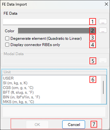
Figure 3.151: Description of parameters in the FE Data Import dialog
| Parameter | Description |
| 1. FE Data | Use to select the FE data file. NASTRAN (*.dat and *.bdf) and Workbench mesh (*.inp and *.cdb) file formats are available in this step. The FE data file contains the information about the finite element, property, node, and material. |
| 2. Color | Use to set the color of the FE body. |
| 3. Degenerate element (Quadratic to Linear) | Use to convert a 2nd order element to a linear element. |
| 4. Display connector RBEs only | Use to display only RBEs that include Static Correction Mode in the working window. Datasets excluding displayed RBEs are not visible in the working window, but the navigator window contains the hidden sets. This enables handling FEs in a simple form by showing only the RBEs related to connectors. This is available for FE input files from the Ansys Mechanical application (*.inp, *.cdb, *.dat) using dfModal. |
| 5. Modal Data | Use to set the modal information. This option is introduced in Modal FE Body Creation in a Mesh (Import FE Data). |
| 6. Unit | Use to set the unit system for the FE data file. |
| 7. Control buttons | If all necessary parameters are set, these buttons are enabled. For more information about the control buttons, refer to Entity Creation. |