

The Crystal Plasticity (CP) Microstructure Add-on provides an efficient solution for creating highly realistic 3D microstructures that capture the grain geometry and texture of materials.
Engineers often face the challenge of generating accurate microstructural models for use in crystal plasticity simulations, which involve multiple steps, including preprocessing, analysis, and postprocessing. The CP Microstructure Add-on simplifies this process by offering a seamless workflow for creating voxelated Representative Volume Elements and generating input files for ANSYS analyses. It serves as a preprocessing framework for crystal plasticity (CP) simulations in Mechanical APDL.
In this tutorial, you will generate a voxelated Representative Volume Element (RVE) model from a microstructural map by using the capabilities of the CP Microstructure Add-on.
| Applicable Products | Workbench and Mechanical applications |
| Licenses Required | Ansys Mechanical Enterprise |
| Help Resources | Crystal Plasticity (CP) Microstructure Add-on |
| Tutorial Files | CPMicrostructureTutorial01.zip |
This tutorial guides you through the following topics:
- 33.1. Access Data Files
- 33.2. Load the CP Microstructure Materials Library
- 33.3. Load the CP Microstructure Add-on
- 33.4. Change Units to Microns
- 33.5. Insert a CP Microstructure Object into Model
- 33.6. Load the EBSD File
- 33.7. Generate and View Grain Statistics
- 33.8. View the Microstructural Map and Grain Statistical Plots
- 33.9. Specify RVE Parameters
- 33.10. Assign Material
- 33.11. Generate Element and Material Data Files
- 33.12. Override Grain Statistics Data and Regenerate Files
Download the Zip file for this tutorial from the Ansys customer site and extract the files to a folder. CPMicrostructureTutorial01.zip contains the following files:
- ebsd_316L_500x500.ang
Experimental data (grain size, grain distribution, and texture within a material) obtained from the Electron-Backscattered Diffraction (EBSD) technique.
- RefStat.json
Grain statistical reference file (.json format), which stores grain statistical data for the material.
The first step in this tutorial is to load the materials library for the CP Microstructure add-on. This materials library is included in the Mechanical application installation. It contains material models and sample materials that you will need for this tutorial. The steps to import this library depend on which application you are using.
Go to a tutorial topic:
Workbench
Mechanical Application Opened Independently
Follow these steps to create a project in Workbench, import the CP Microstructure materials library into the project's Engineering Data Module, and open the Mechanical application from Workbench:
Open Ansys Workbench.
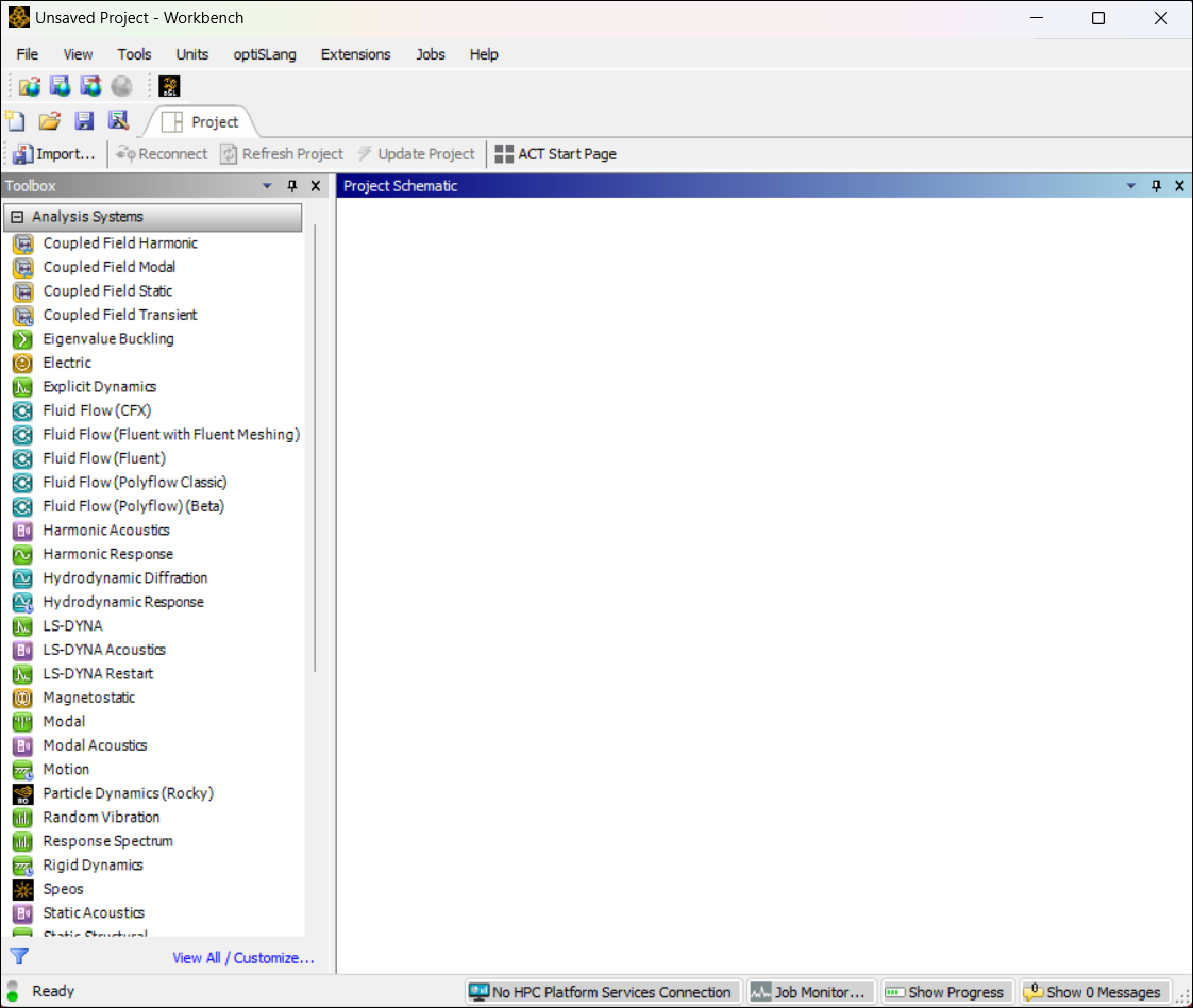
From the toolbox on the left-hand side of the window, double-click or drag-and-drop a Static Structural system into the Project Schematic window.
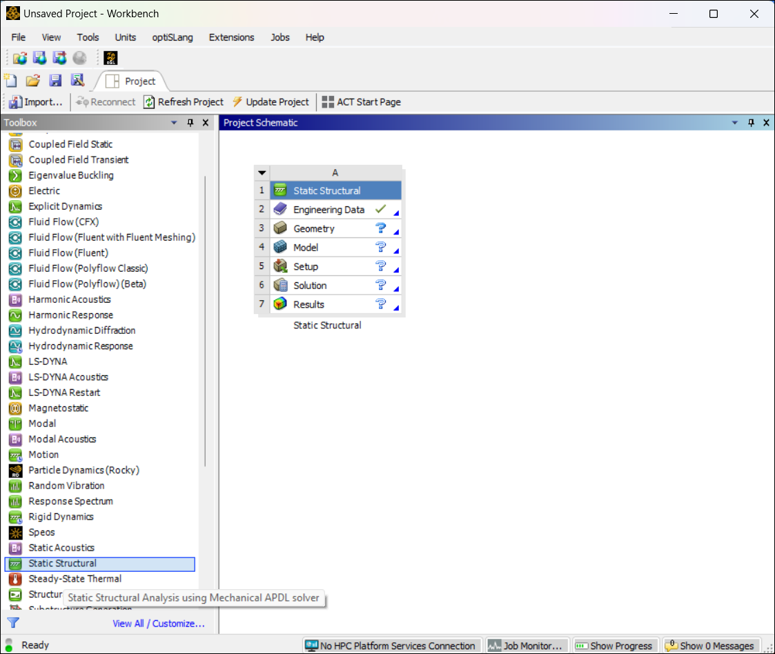
Double-click the Engineering Data module to open it.
Choose > . The Open dialog box is displayed.
Navigate to the following directory:
ANSYS_INSTALL_DIR\aisol\WBAddins\MechanicalExtensions\CPMicrostructure\MaterialsLibrary\
where ANSYS_INSTALL_DIR is the directory where you installed the Ansys software.
Select the MaterialLibrary_CPMicrostructure.xml file and click . The Engineering Data module imports the library.
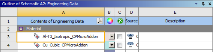
Verify that the imported material Al-T3_Isotropic_CPMicroAddon is listed under Contents of Engineering Data in the Engineering Data module:
Close the Engineering Data tab to return to the Project window.
Load the Engineering Data materials and material models into the Mechanical application. Do the following:
In the Project window, right-click the Engineering Data module to display a drop-down menu.
Select . This imports the CP Microstructure materials library into your Mechanical model.
Choose > and save your new Workbench project as cp_micro_tutorial.
Double-click Model in the Static Structural analysis system to open the Mechanical application.
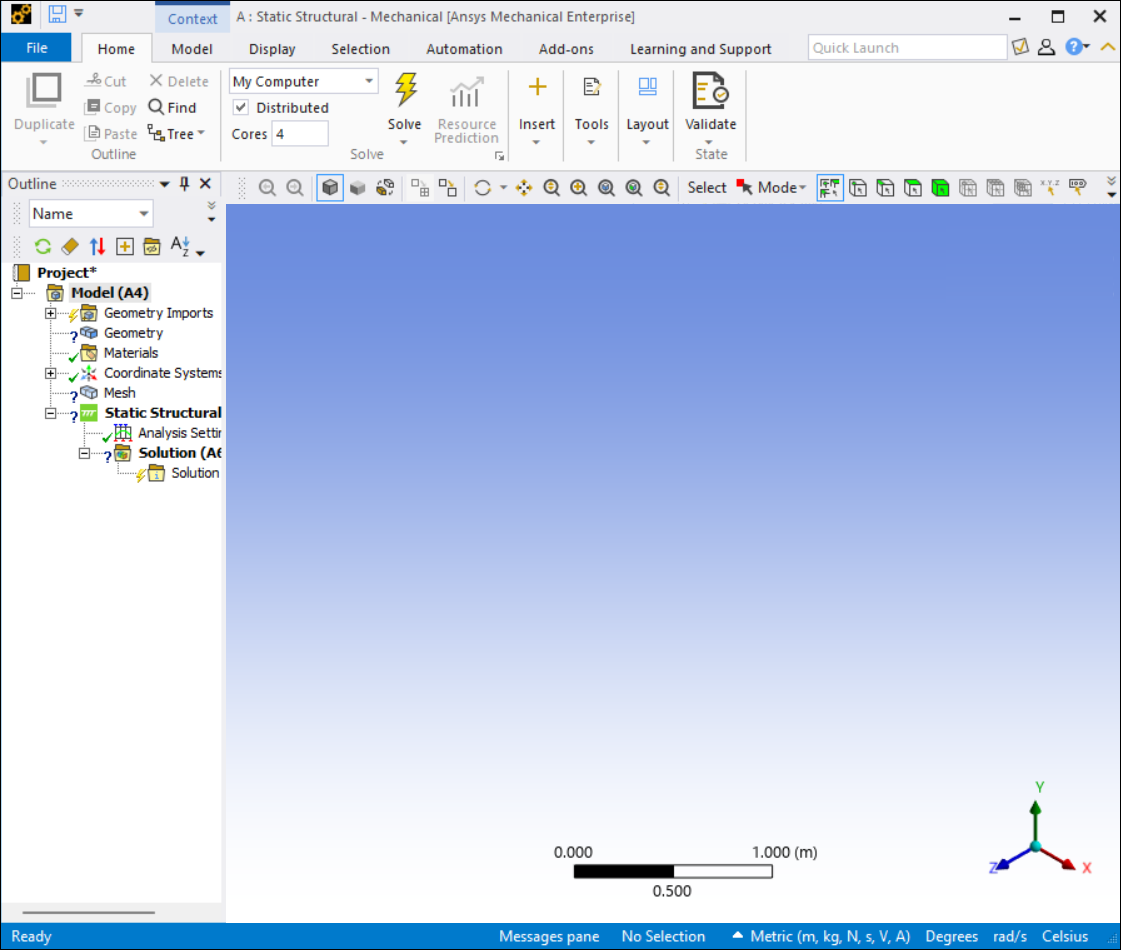
Follow these steps to open the Mechanical application independently, create a new project, and import the materials library for the CP Microstructure Add-on.
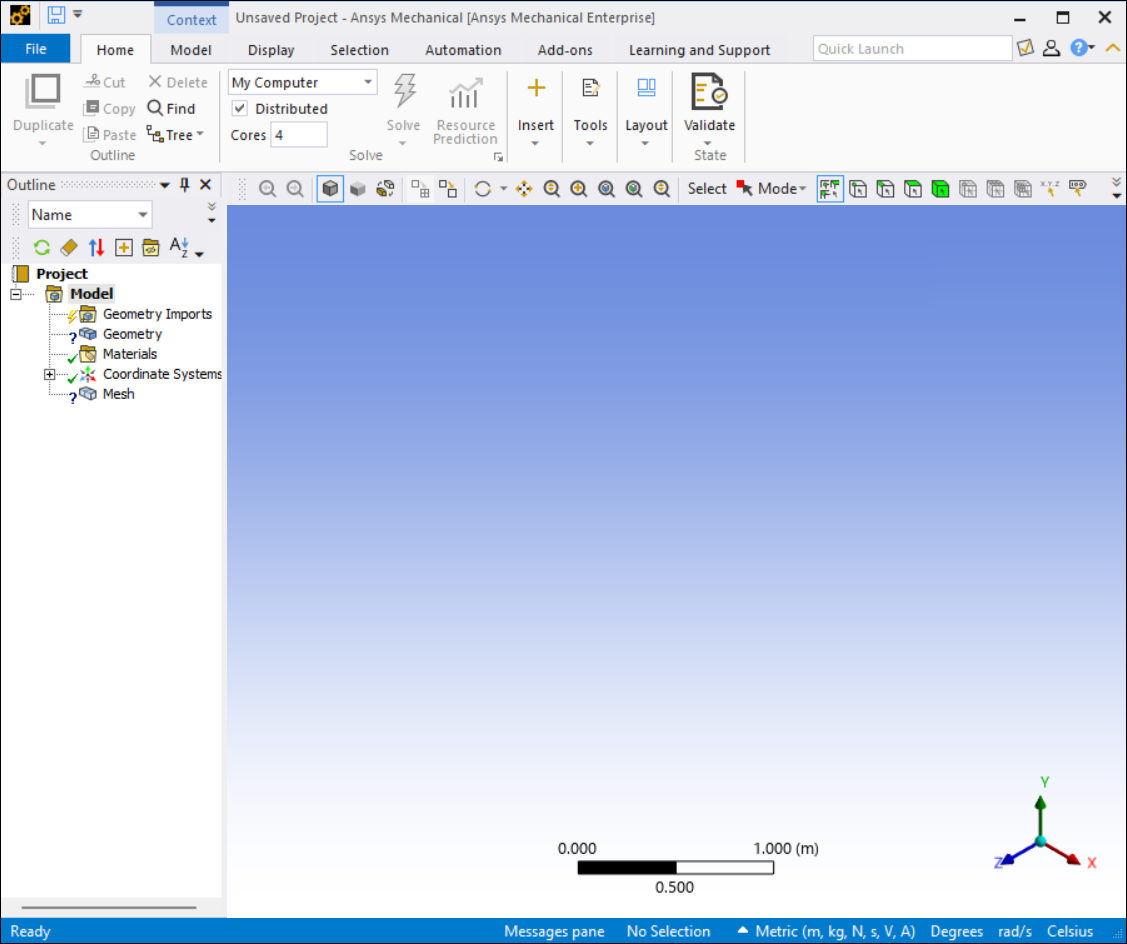
Run the Mechanical application independently of Workbench.
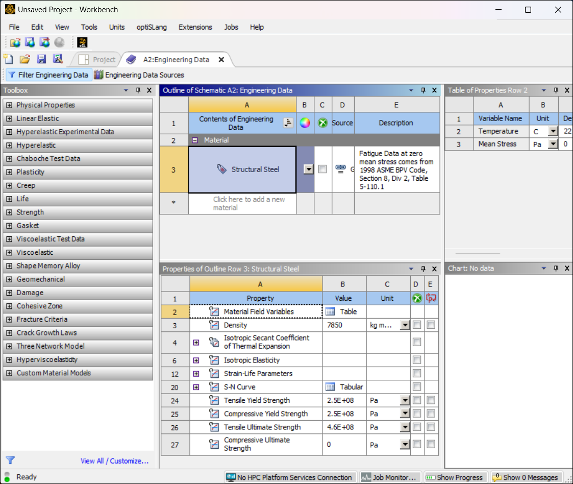
Click . The Mechanical application appears as shown below.
In the Outline pane, left-click Materials and select from the menu. The Open dialog box is displayed.
Navigate to the following directory:
ANSYS_INSTALL_DIR\aisol\WBAddins\MechanicalExtensions\CPMicrostructure\MaterialsLibrary\
where ANSYS_INSTALL_DIR is the directory where you installed the Ansys software.
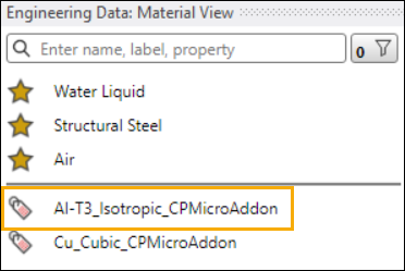
Select the MaterialLibrary_CPMicrostructure.xml file and click Open. The Mechanical application imports the library.
Verify that Al-T3_Isotropic_CPMicroAddon is listed in the Engineering Data Material View:
Choose > and save your new project as cp_micro_tutorial.
The CP Microstructure Add-on runs in the Mechanical application. To make its capabilities available, click the icon in the Add-ons ribbon. The icon will be highlighted in blue, indicating that the add-on is loaded.
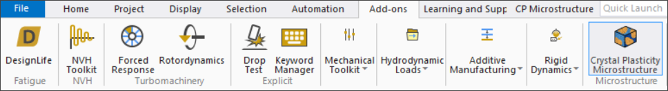
Once the add-on is loaded, the menu is visible. Click the menu to display the Crystal Plasticity Microstructure toolbar.
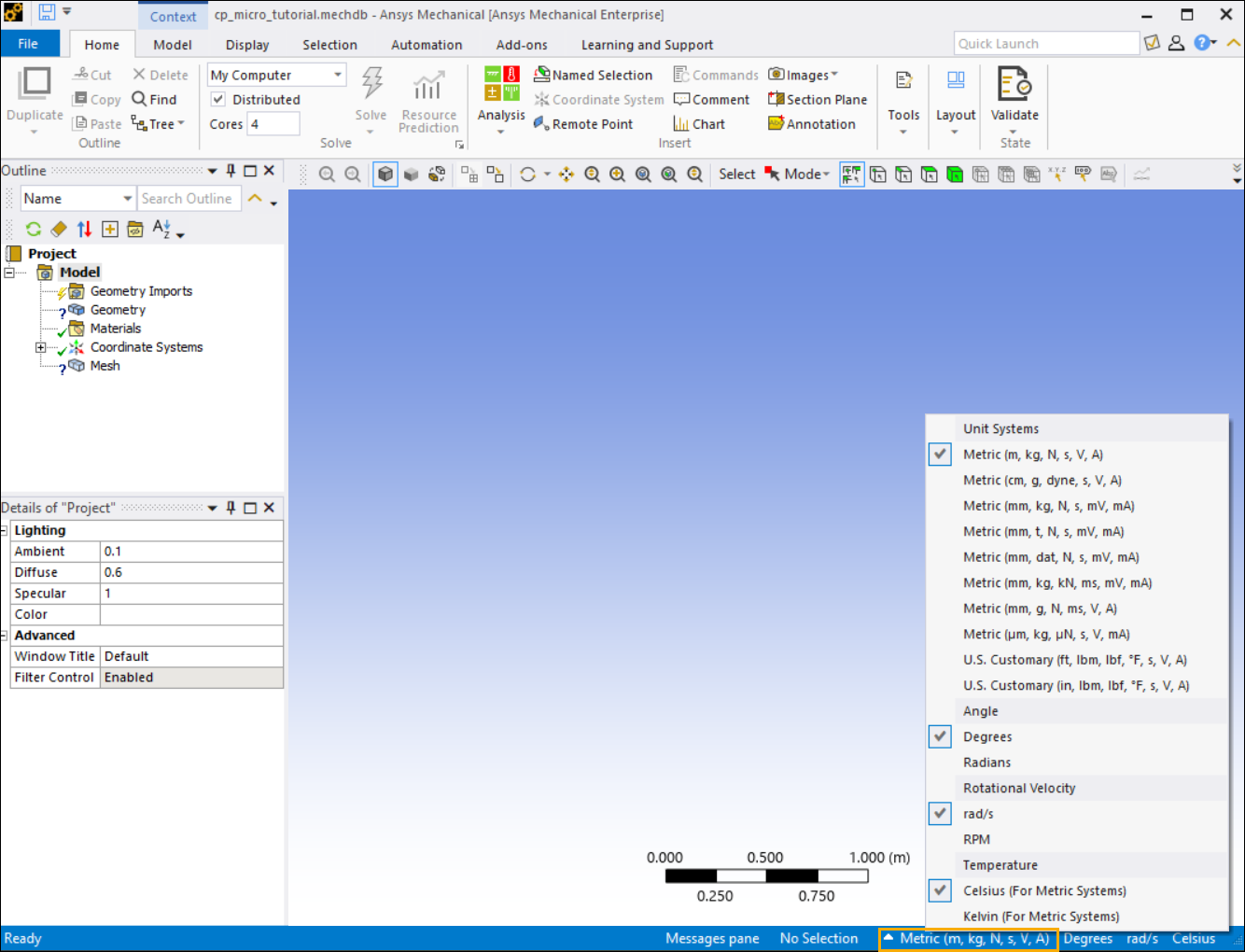
Change the base units of measurement for your project to microns (μm), which are typically used in crystal plasticity analyses.
In the right-hand side of the status bar (located at the bottom of the Mechanical application window), click the current units of measurement (by default, Metric (m, kg, N, s, V, A)). A menu of available unit systems appears.
Select from the Unit Systems menu.
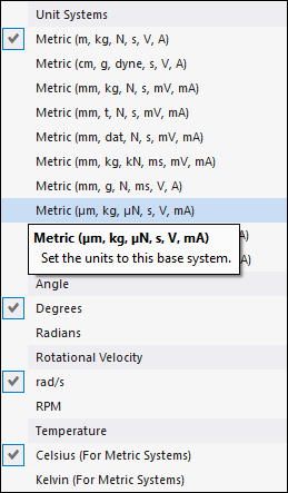
The status bar now shows the new unit system for the project ().
Next, insert a CP Microstructure object into your Model tree.
To add a CP Microstructure object to the project, do one of the following:
Click the Crystal Plasticity Microstructure icon
 in the ribbon.
 Right-click the Model object to open the context menu, then choose >.
Verify that the CP Microstructure object is inserted to the Model tree. The new object has a question mark (?) state, which indicates that one or more fields have not yet been completed or contain invalid information.
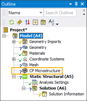
Note: You do not need to import a geometry to use the CP Microstructure object.
The next step in this tutorial is to load an Electron-Backscattered Diffraction (EBSD) file into the CP Microstructure object.
An EBSD file contains Euler angles that specify the orientation of each grain in the material. The CP Microstructure Add-on uses this information to compute grain statistics and a microstructural map of the material.
Click the CP Microstructure object to display its Details pane.
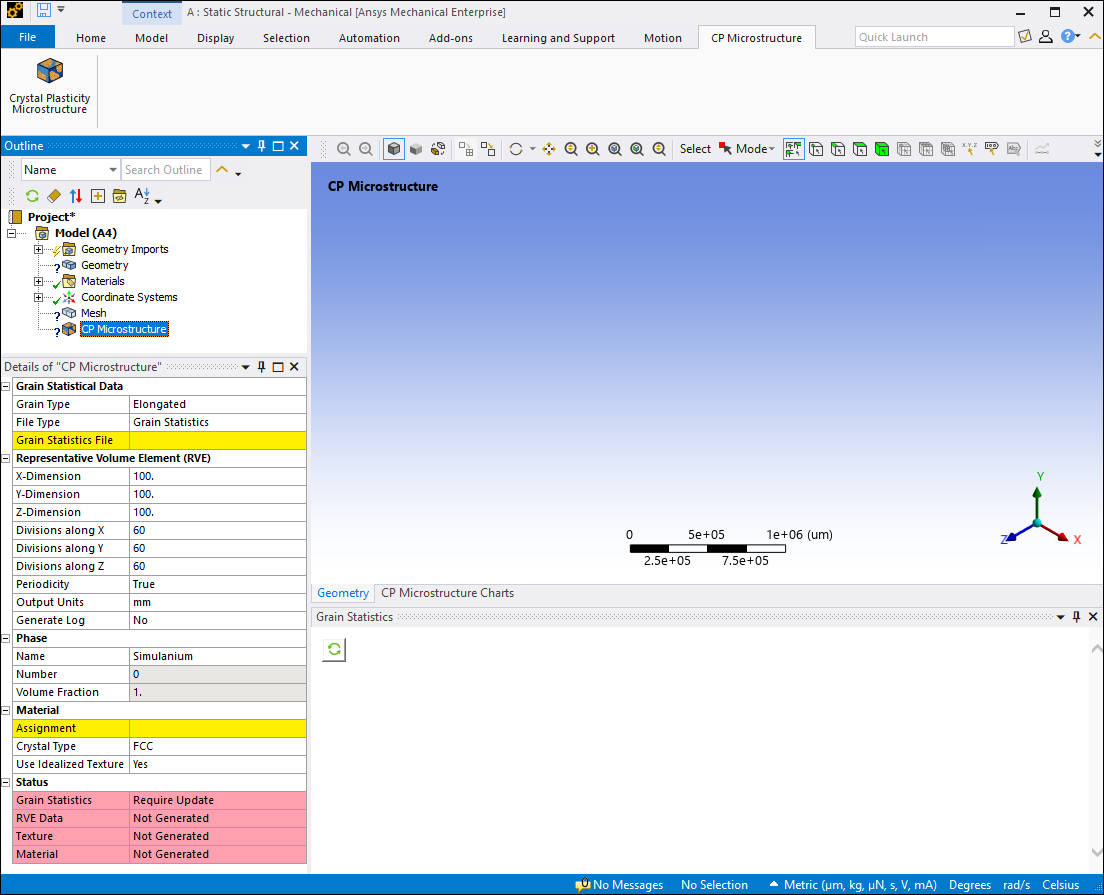
Under the Grain Statistics header in the Details pane, set the File Type to EBSD.
Click the yellow field next to EBSD File to open the system's file selection dialog. Browse to the folder where data files for this tutorial are saved (see Access Data Files). Select the file ebsd_316L_500x500.ang and click Open.
Use your system file dialog to verify that the above EBSD file is copied to the user_files folder in the working directory of the project. The add-on automatically creates a subfolder SysA_MicrostructureXX (where XX is the internal ID of the CP Microstructure object) to store the files for each CP Microstructure object. A copy of the EBSD file is automatically saved in this folder as GrainStat_EBSD.ang
After you finish loading the EBSD file, generate grain statistics. This step reduces the number of grains to an adequate quantity for reproducing the equivalent statistics for the crystal plasticity analysis.
Click the button
 in the Grain
Statistics window. This extracts grain statistical data from the
EBSD file.
in the Grain
Statistics window. This extracts grain statistical data from the
EBSD file. The following figure shows the computed grain statistics. Depending on your computing resources, the extraction process may take several minutes to complete.
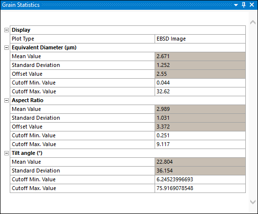
Note: The Grain Statistics worksheet uses statistical data fitting. The data that you see after loading the EBSD file might not be exactly the same as the statistics shown in this tutorial.
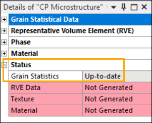
Verify that the Grain Statistics status is changed to Up-to-date. The Status heading under the Details view shows the status of each step in the CP Microstructure modeling process. Incomplete steps are highlighted in red.
After you load the EBSD file, you can view plots of grain characteristics and statistics.
Note: The Grain Statistics plots use statistical data fitting. The plots that you see might not be exactly the same as the plots shown in this tutorial.
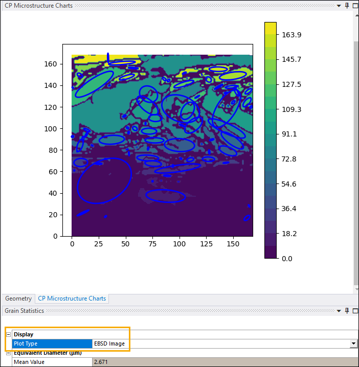
Click the CP Microstructure Charts tab to view a microstructural map of the material. In this map, grains are color-coded according to their respective orientation angles. The Plot Type in the Grain Statistics worksheet at the bottom of the window should be set to .
In the Grain Statistics worksheet, change the Plot Type to . The following data is plotted in the CP Microstructure Charts pane (replacing the microstructural map).
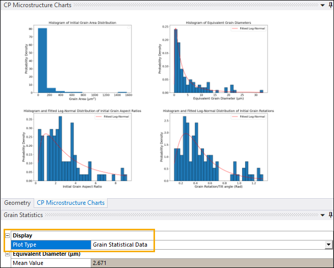
Review the histogram and fitted log-normal distributions of grain area, equivalent diameter, aspect ratio, and rotations.
After you view the grain statistics plots, set the Representative Volume Elements (RVE) for the CP Microstructure object. These values determine the number and size of the voxels in your model (and therefore the elements in the mesh), the units of measurement, and other meshing parameters.
Click the CP Microstructure object to display the Details view.
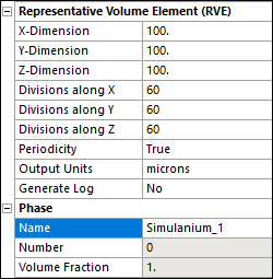
Enter the following values in the fields under Representative Volume Elements (RVE):
- X-Dimension, Y-Dimension, and Z-Dimension
100
- Divisions along X, Divisions along Y and Divisions along Z
60
- Periodicity
True
- Output Units
microns
- Generate Log
No
Under Phase, set Name to Simulanium_1.
When you are finished, the Representative Volume Elements (RVE) and Phase parameters should look like this.
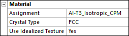
Next, assign a material to the CP Microstructure object. Set the following material properties in the Details pane under the Material header:
Click the yellow field next to Assignment and select from the drop-down menu of CP Microstructure materials.
Note: If this material is not listed on the menu, do one of the following:
If you opened the Mechanical application from Workbench, right-click the Materials object and choose from the drop-down menu. This reloads material definitions from the Engineering Data module.
If you opened the Mechanical application independently, follow the steps in Import Materials Library into Mechanical Application to reload the material library.
Set Crystal Type to .
Set Use Idealized Texture to .
When you are finished, the Material parameters should look like this.
After you specify RVE parameters and assigned a material, you can generate the element (mesh) and material data files:
Right-click the CP Microstructure object and select Generate Data from the drop-down menu.
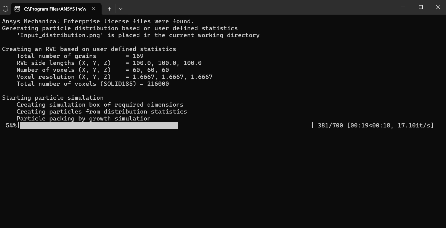
Depending on your available computing resources, this process may take some time. You can monitor the progress in the console window and the status bar.
Unfortunately, the following error message appears at the bottom of the Mechanical application window when you try to generate the CP Microstructure data:
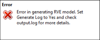
The parameters from the previous section did not produce a good solution.
You will need to view the error log to see what went wrong. Set the Generate Log property in the CP Microstructure object Details pane to Yes. This records solution messages in a log file.
Try to regenerate the files with logging turned on. Right-click the CP Microstructure object and select Generate Data again.
Note: Setting Generate Log to Yes slows down the process of generating CP Microstructure files because the application must continuously write information to the output.log file. Ansys recommends that you only use this option only if there is an error and you need to log and read the error messages to take corrective action. (In other words, for cases similar to the one in this tutorial.)
The same error message as earlier appears. However, this time the CP Microstructure add-on logged the messages produced during the data generation process. After the console window closes, right-click the Project object in the Outline tree and choose Open Project Files Directory from the drop-down menu. The system file dialog appears.
Navigate to the folder user_files\SysA_MicrostructureXX.
Open the output.log file with your favorite text editor. You should see the following error message near the end of the file:
Creating an RVE based on user defined statistics
Grains will not be voxelated well!
Please increase the voxel numbers (OR) decrease the RVE side lengths
The analysis you've done so far produced grain sizes that cannot be efficiently divided up into three-dimensional units (voxelated) or meshed. You can address this problem in three different ways:
Import a grain statistics file to override the statistics that were computed from the EBSD file. You can specify the file name via the Override Data field under Grain Statistical Data according to the guidelines in Grain Statistical Data in the Mechanical Add-ons Guide. This option is only available if you imported an EBSD file.
Change the RVE parameters (such as Number of Divisions or Dimensions) according to the guidelines in Specifying Representative Volume Element (RVE) Parameters in the Mechanical Add-ons Guide. This changes the parameters for generating a mesh.
Adjust the Cutoff Min. Value and Cutoff Max Value for Equivalent Diameter in the Grain Statistics Worksheet according to the guidelines in Setting Cutoff Values for Grain Attributes in the Mechanical Add-ons Guide. This eliminates grain size outliers and ensures that the grain dimensions are consistent enough to generate a mesh.
In this part of the tutorial, you will import a grain statistics file to override the equivalent diameter data from the EBSD file. This specifies a more uniform grain size for the crystal plasticity analysis. You will then regenerate the CP Microstructure files.
First, import a grain statistics file to override the statistics computed from the EBSD file. The file specifies new equivalent diameter values for the grains in the material, which will produce a good mesh.
In the CP Microstructure Details pane under Grain Statistical Data, set Override Data to Yes.
Click the yellow field next to Select File to launch the system file open dialog.
Select the grain statistical reference file RefStat.json from the tutorial files folder and click . This file contains reference data for specifying the equivalent diameter of the grains.
Click the button
in the Grain
Statistics window. This loads the new equivalent diameter
data from the RefStat.json file. Verify that the equivalent diameter values in the Grain Statistics Worksheet match the equivalent diameter values from the RefStat.json file.
|
RefStat.json file {
"Equivalent Diameter": {
"mean": 0.557,
"offs": 7.455,
"cutoff_min": 0.062,
"cutoff_max": 66.958,
"std": 2.876
}
}
|
Grain Statistics Worksheet 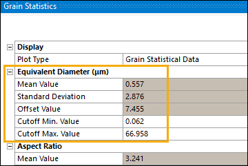 |
After you import the new equivalent diameter values, regenerate the CP Microstructure files.
Do not change the RVE parameters that you specified earlier in the tutorial.
Set Generate Log to No.
Regenerate the CP Microstructure data files. Right-click the CP Microstructure object and select from the drop-down menu.
Depending on your available computing resources, this process may take some time. You can monitor its progress in the console window and the status bar.
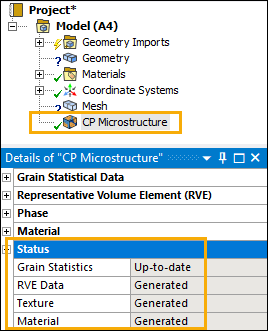
When the CP Microstructure add-on is done generating data, a check mark appears next to the CP Microstructure object in the Model tree. The Status fields in the Details pane are no longer highlighted in red and show that RVE Data, Texture data, and Material data are now Generated.
Finally, check whether the following output files are available in the user_files/SysA_MicrostructureXX folder in the working directory of your project:
apdl_px_XXXgrains_voxels.dat – Contains the generated geometry and mesh data for the microstructure. XXX is the number of grains in the output file.
MatAssignment.dat – Contains the material assignments for the grains in the microstructure.
These files can be used as input for a crystal plasticity analysis with Mechanical APDL.