


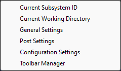
- Current Subsystem ID
Set current subsystem ID.
- Current Working Directory
Set current working directory.
- General Settings
Launch the General Settings interface.
- Post Settings
Launch the interface for Post-processing settings
- Configuration Settings
Launch Configuration Settings interface.
- Toolbar Manager
Customize toolbars.
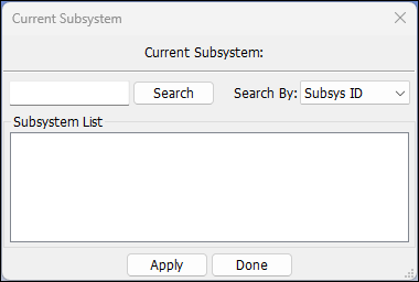
- Search
Search subsystem from subsystem list.
- Search By
Search subsystem by name or ID.
- Subsystem List
Click item to select.
- Done
Set current subsystem.
- Apply
Apply changes.
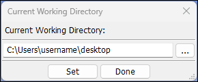
- Current Working Directory
Select a directory from the system.
- Set
Set the working directory.
- Done
Close the dialog after setting the working directory.
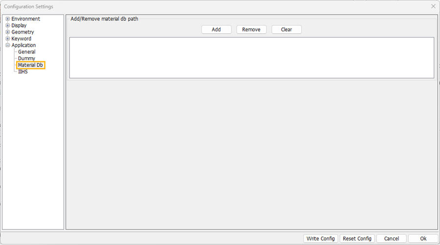
This Configuration Settings interface provides a convenience for modifying and previewing parameters in the preference file (.lsppconf).
The .lsppconf file is located in user's AppData directory for Windows and home directory for Linux individually, which stores information regarding the LS-PrePost configuration and is automatically saved every time LS-PrePost exits.
Tip: When updating to a new version of LS-PrePost, you don't have to delete your old .lsppconf file to get the new features because the software will refresh it automatically.
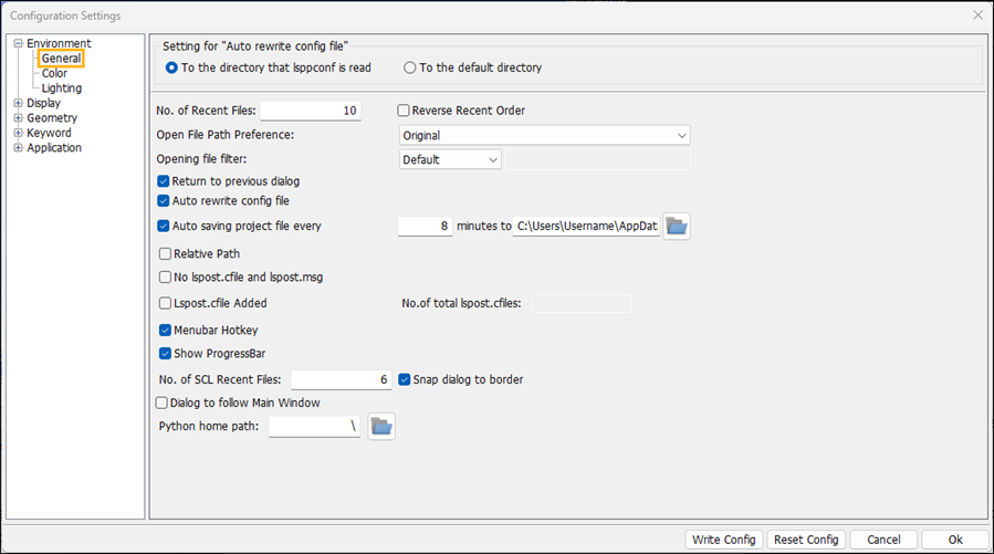
- No.of Recent Files
Set number of entries in File->Recent.
- Reverse Recent Order
Reverse the order of recording recent files.
- Auto rewrite config file
Automatically rewrite the configuration file (lsppconf).
- Relative Path
Set relative path for the command file.
- No lspost.cfile and lspost.msg
Stop lspost.cfile and lspost.msg from being generated.
- Lspost.cfil Added
Add more lspost.cfil files in the same directory.
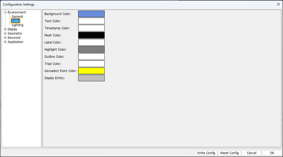
- Background Color
Click to set background color.
- Text Color
Click to set text color.
- Timestamp Color
Click to set timestamp color.
- Mesh Color
Click to set mesh line color.
- Label Color
Click to set label color.
- Highlight Color
Click to set highlight color.
- Outline Color
Click to set outline color.
- Triad Color
Click to set triad color.
- Genselect Point Color
The color for point objects, such as the nodes in a model, when selected using the general selection tool.
- Display Entity
Defines the color of the Entity when displayed in the Display Entity user interface. The entity can be shown in color with all other visible parts displayed in gray. This allows you to easily locate the entity in the model.
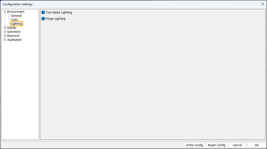
- Two-Sided Lighting
Set two-sided lighting.
- Fringe Lighting
Set fringe lighting.
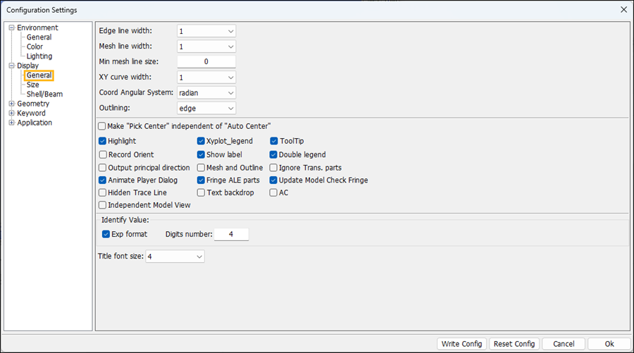
- Edge line width
Select edge line width.
- Mesh line width
Select mesh line width.
- Min mesh line size
Avoid draw mesh lines on parts with an average element size smaller than this value (in pixels).
- XY curve width
Select XY curve line width.
- Coord Angular System
Select coordinate system in radian or degree.
- Outlining
Set draw model outline mode.
- Highlight
Highlight selected entities.
- Xyplot_legend
Set xyplot legend.
- ToolTip
Show/no tooltip.
- Record Orient
Record to lspost.cfile with orientation (quat/zoom/pan).
- Show label
Show node label on/off only for trace dialog.
- Double legend
Show both fringe and vector color bars at the same time.
- Output principle direction
Output principal strain/stress direction to lspost.msg while fringing vector plot.
- Mesh and Outline
Draw mesh line and outline together.
- Ignore Trans. parts
Ignore transparent parts in drawing outline.
- Animate Player Dialog
Enable/disable the animate player dialog when the transparent player bar is shown.
- Fringe ALE parts
Select this option to apply the fringe on the ALE parts when clip mode of section-cut is enabled.
- Update Model Check Fringe
Automatically update model check fringe after model changes when Model Check Fringe is on.
- Hidden Trace Line
Hidden trace line when drawing the trace of node, point and CG.
- Text backdrop
Use a colored backdrop on text labels in the main window.
- AC
Select this option to send the command "ac" after switching the model ("model select i")
- Independent Model View
Each model has its own project view.
- Horizontal Legend
Show the legend in a horizontal direction.
- Exp format
Select to show exponent format for identify value.
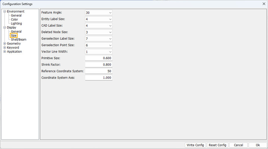
- Feature Angle
Select feature angle value.
- Entity Label Size
Input entity label size.
- CAD Label Size
Input cad label size.
- Deleted Node Size
Set deleted node size.
- Genselection Label Size
Set the Genselection dialog label size.
- Genselection Point Size
Set Genselection point size.
- Vector Line Width
Set the width of the vector line.
- Primitive Size
Input primitive size.
- Shrink Factor
Input shrink factor.
- Reference Coordinate System
Input Reference Coordinate System size.
- Coordinate System Axis
Scale factor of the Coordinate System Axis size.
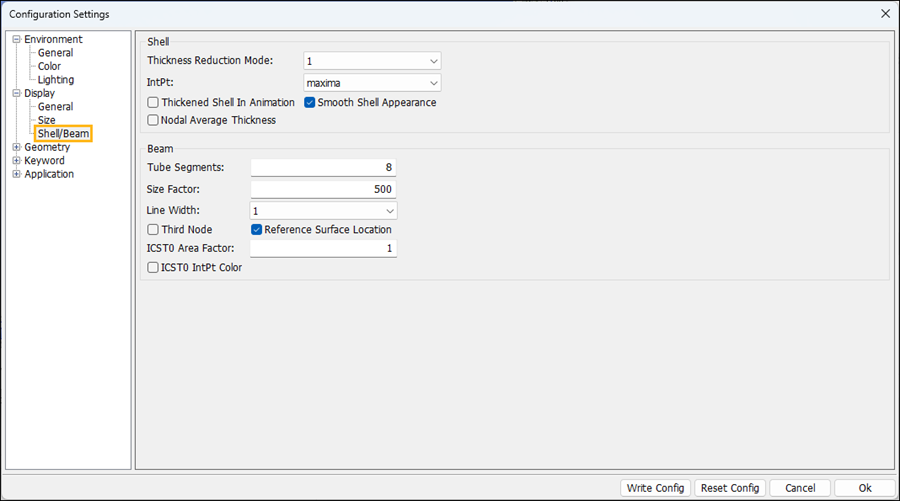
- Thickness reduction mode
Select shell thickness reduction mode.
- IntPt
Select the shell Integration point location for fringing.
- Thickened Shell In Animation
Show thickened shell In animation.
- Smooth Shell Appearance
Smooth shell thickness appearance at common edge.
- Nodal Average Thickness
Use the node or element average thickness to represent shell appearance.
- Tube Segments
Change the number of segments to use when drawing a beam as a tube.
- Size Factor
Input beam size factor.
- Line Width
Draw beam line width.
- Third Node
Draw beam third node.
- ICST0 Area Factor
Area factor (0,1] at each integration point if ICST=0 is specified in *integration_beam.
- ICST0 IntPt Color
This setting is applicable when the beam section is defined using the keyword *INTEGRATION_BEAM where ICST=0. Select this check box to draw the beam integration point with the defined PID color instead of the default PID color. This allows the color at the integration point to differ from other integration points and improves the visualization of the beam section.
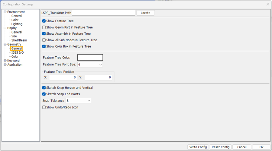
- LSPP_Translator Path
Points to the LSPP Translator file, which is needed for importing CAD files through the File > Import > CAD menu.
- Show Feature Tree
Show or hide feature tree.
- Show Geom Part in Feature Tree
Show or hide feature tree geometry part.
- Show Assembly in Feature Tree
Show or hide feature tree assembly.
- Show All Sub Nodes in Feature Tree
Show or hide all sub nodes in the feature tree.
- Show Color Box in Feature Tree
Show or the hide color boxes in the feature tree.
- Feature Tree Color
Click to set feature tree color.
- Feature Tree Font Size
Click to set feature tree font size.
- Feature Tree Position
X-position and Y-position of feature tree.
- Sketch Snap Horizon and Vertical
Turn horizontal and vertical point snapping on and off in sketch.
- Sketch Snap End Points
Turn end point snapping on and off in sketch.
- Snap Tolerance
Select snap tolerance.
- Show Undo/Redo Icon
Show or hide the undo and redo buttons in the graphics window, which work for geometry operations.
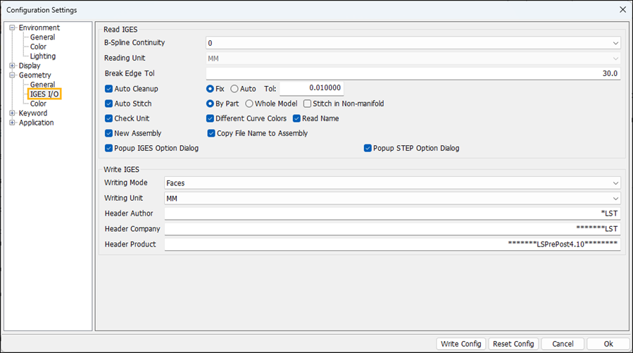
- B-Spline Continuity
Select an option for managing the continuity of B-spline curves (IGES entities 106,112 and 126):
Do not split the B-spline curve. (No modification.)
Split the B-spline curve into pieces, each with C1 continuity.
Split the B-spline curve into pieces, each with C2 continuity.
- Reading Unit
Select reading IGES unit.
- Break Edge Tol
Input breaking edge tolerance.
- Auto Cleanup
Whether need to clean up shapes.
- Fix
Using fix tolerance to cleanup shapes.
- Auto
Using auto tolerance to cleanup shapes.
- Tol
Input auto cleanup tolerance.
- Auto Stitch
Whether need to stitch faces within a part or stitch faces for the entire model (connecting parts together), and whether or not to stitch in non-manifold.
- Check Unit
Automatically detect IGES file unit.
- New Assembly
Read the shape into a new assembly.
- Different Curve Colors
Assign curves different colors when reading the IGES file.
- Read Name
Extract part name from the IGES file.
- Copy File Name to Assembly
Copy current IGES file name into the new assembly.
- Popup IGES Option Dialog
Popup option dialog when reading an IGES file.
- Popup STEP Option Dialog
Popup option dialog when reading a STEP file.
- Writing Mode
IGES file writing mode "Faces" or "BRep".
- Writing Unit
Select writing IGES unit.
- Header Author
Input writing file head author info.
- Header Company
Input writing file head company info.
- Header Product
Input writing file head product info.
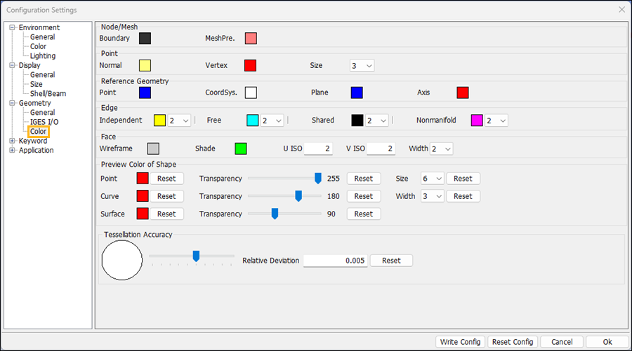
- U ISO
Input geometry shape face ISO U curves number.
- V ISO
Input geometry shape face ISO V curves number.
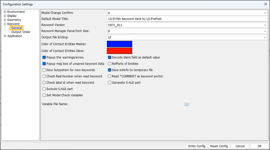
- Model Change Confirm
This option is for the Model Checking procedure. It determines if LS-PrePost should recheck the model after keyword data, in the Keyword Input Form, has been changed. You can select either: 0 (determined by user), 1 (accept changes but do not recheck model), or 2 (accept changes and recheck model).
- Default Model Title
Default model title if no title (*TITLE) is loaded.
- Keyword Version
Select Keyword version.
- Popup the warning/errors
Pop-up the message dialog to prompt warnings and errors when LS-PrePost reads the keyword file.
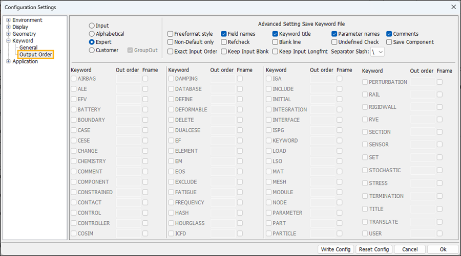
- Input
Output keyword order by input order.
- Alphabetical
Output keyword name in alphabetical order.
- Expert
Output by expert recommended sequence.
- Customer
Output keyword name in customer order.
- GroupOut
Output keyword as group ,such as *PART,*SECTION,etc.
- Freeformat style
Output data in Free Format/Fix Format.
- Field names
Output keyword field names.
- Keyword title
Output keyword *Title.
- Parameter names
Output parameter names instead of real data.
- Comments
Output keyword comments.
- Non Default only
Not output zero if only default value is zero.
- Refcheck
Output data with all reference data.
- Blank line
Output blank if all line fields or all right side fields are 0 or 0.0.
- Undefined Check
Output Undefined link in current output with 0.
- Save Component
Select to save component part.
- Exact Input Order
Select to save exactly the same as the input order.
- Keep Input Blank
Select to keep field same as input.
- Keep Input Longfmt
Select to keep the keyword long format as input when writing the model as normal format.
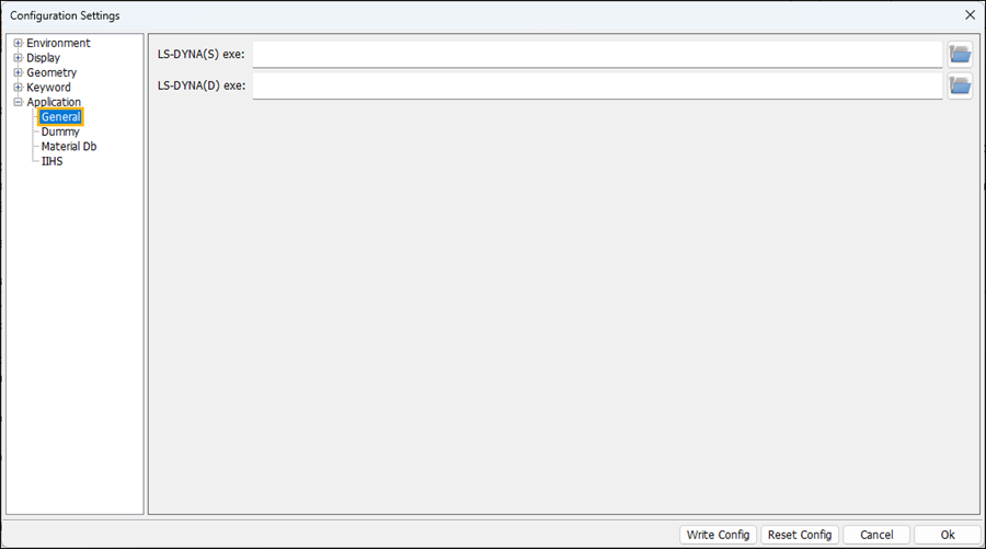
- LS-DYNA(S) exe
Define the file path for the LS-DYNA single precision executable.
- LS-DYNA(D) exe
Define the file path for the LS-DYNA double precision executable.
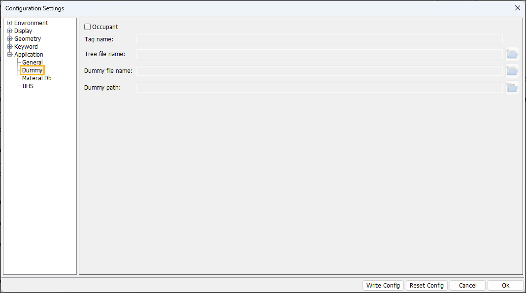
- Occupant
Click to enable/disable dummy info widgets.
- Tag name
Input tag name.
- Tree file name
Click to browse dummy tree file name.
- Dummy file name
Click to browse dummy file name.
- Dummy path
Click to browse dummy path.
The menu provides a user interface to customize the right toolbar and bottom toolbar. The configuration file (Configure_Toolbar.cfg) will be saved into the home directory (for Linux) or %appdata%/LSTC/LS-PrePost directory (for Windows).
Tip: When updating to a new version of LS-PrePost, you don't have to delete your old Configure_Toolbar.cfg file to get the new features because we will automatically refresh it.
- Sample
A sample to show how to customize toolbars.
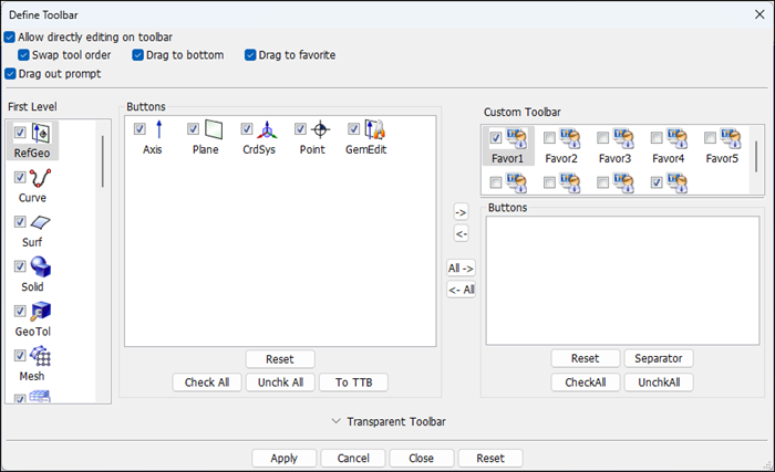
- Allow directly editing on toolbar
Allow directly dragging the icon to bottom toolbar, favor1 and favor2.
- Drag out prompt
Give prompt or not when dragging icon.
- Transparent Toolbar
Use the "Transparent Toolbar" section to create a custom toolbar that is transparent and floats in the main window. You can right-click the transparent toolbar in the main window to change its appearance and move it to a convenient location.