


A sub-volume is a volumetric part of the simulation domain. It is a concept used in Forte's Automatic Mesh Generation (AMG) approach. Sub-volumes can be used to identify distinct and individual regions in the domain. Once created, sub-volumes have several use cases:
Use sub-volumes in mesh controls: Sub-volumes can be used as “secondary volumes” in mesh controls. See Mesh Controls for Automatic Meshing for details.
Use sub-volumes in initialization: Since sub-volumes identify distinct regions of the domain, they can be used as the basis for defining initial conditions. See Configuration of Initialization Regions for Automatic-mesh Generation for details.
Use sub-volumes in monitor probes: You may monitor spatially-averaged solution variables in a sub-volume region. See Probes for Instantaneous, Spatially Averaged Data for details.
To create a sub-volume, go to the Geometry node (see Geometry Node) and select the Sub-volumes
sub-node  . Then, click New Sub-Volume
  .
.
Region Definition
On the sub-volume editor panel, select the surfaces in the geometry that surround the desired volume to isolate.
Ideally, the selected surfaces are watergight, and they perfectly enclose the desired sub-volume. However, you will likely encounter the following situation:
There might be one or multiple small holes on a certain surface.
Since the watertight geometry will contain continuous manifolds, there will inevitably be a boundary at which the selected surfaces for the desired sub-volume meet with unselected surfaces.
To deal with these situations, a surface capping technique will be applied to the selected surfaces to complete the sub-volume creation.
Figure 2.22: Creating a sub-volume in part of a gas exchange port provides an example to illustrate how the second situation is handled by the surface capping technique. In this example, we would like to create a sub-volume for the horizontal cylindrical region, which is part of the gas exchange port. We select the highlighted surface enclosing the desired sub-volume. Note that these selected surfaces are not watertight themselves. The surface capping works and helps create the sub-volume as shown in the figure.
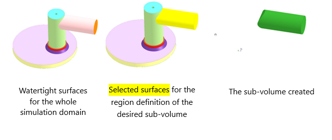
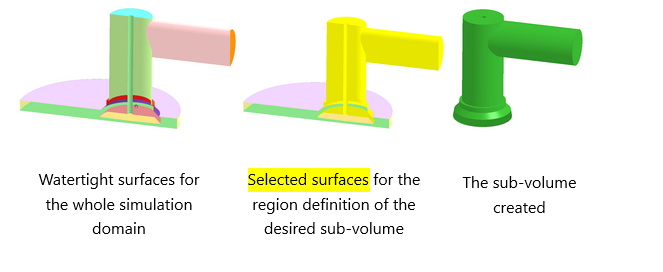
Figure 2.23: Creating a sub-volume in the whole gas exchange port provides another example. Here, a clip plane through the gas exchange port is applied to visualize the inner structure of the port. We select the highlighted surfaces enclosing the desired sub-volume. Surfaces of the valve within the port are also selected. Note that these selected surfaces are not still watertight, but the surface capping works and helps create the sub-volume as shown in the figure.
Note: If the opening in your selected surfaces is too large or too complicated (for example, not on a planar surface), the surface capping might fail.
Material Point
This material point is mainly used when the sub-volume created is used as “secondary volumes” in mesh controls. See Mesh Controls for Automatic Meshing for details.
Here, the material point defines the nature of the mesh control: if the material point is placed within the sub-volume, the control will act on the sub-volume. If the material point is placed outside of the sub-volume (but still within the simulation domain) the control will act on the volume not enclosed by the sub-volume.
Capping Method
Select the method used by the surface capping. Multiple passes is the default and recommended option. Single pass is a legacy option and is not recommended.