


After you have properly defined the blank outline (either an imported curve or a curve created with design tools) and meshed the blank, it appears in the graphics window as shown below. Note that the first cell under Definition is green while the No Mat. label is still red in the second cell, which indicates the blank is defined and you can proceed to the next step, defining the blank material. Also note that the default value of the friction factor, Lub. Coeff. = 0.12, is suitable in most cases for all tool and sheet contacts.
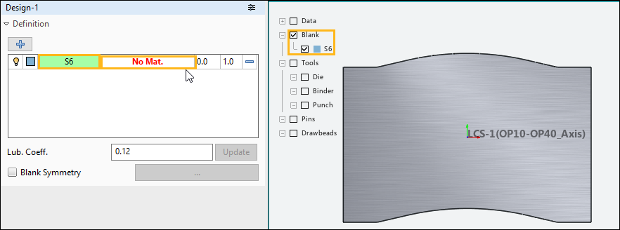
Click the No Mat. cell to open the Material Library task panel, where you can choose a material from the library, import or export a material, or use the Material Editor to define a new material.
To define the blank material follow the steps and the figures below.
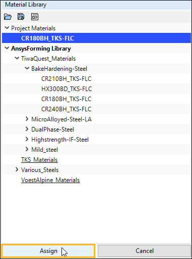
Select a Material
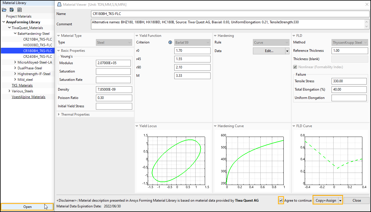
To choose a material from the library, select a material and click Open or double-click a material in the library. This opens the Material Viewer shown below.
If the selected material is subject to a usage license, check the box next to Agree to continue to acknowledge the license and activate the button.
If a material was copied previously to the Project Materials list, you can select the material desired from the Project Materials list.
To import a material, click Material Library task panel. Browse and select your material model, then click .
To define a new material, click to open the Material Editor dialog box.
Note: You can store custom or modified material definitions in a User Material Library for use in multiple projects. For more information, see Creating a User Materials Library.
(Optional) Define the Material's FLD
If you wish to evaluate material formability during postprocessing using a forming limit diagram (FLD), you must define the material's FLD here before you start the simulation.
Important: If you do not define the FLD of the material before the simulation is run, you will have to return to the Blank tab and edit the blank material to include FLD, then re-run the simulation, before you can use FLD to evaluate material formability.
Assign the Material
In the Material Viewer, click Copy+Assign to copy the material definition to the project, assign it to the blank, and return to the Design-n task panel. To copy a material to the project without assigning it at this time, choose from the drop-down menu that is attached to the button.
Note: Any materials you have copied to the project are listed under Project Materials in the Material Library task panel. If needed, you can open the Material Editor by double-clicking any project material.
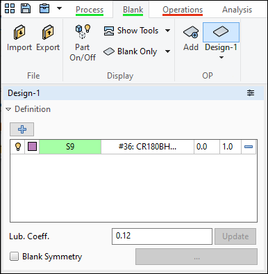
Once you have input all the information required to define the blank, the status bar under the Blank tab appears green as seen in the figure below.
Considerations for Hot Forming
In a Hot Forming project, only materials with defined thermal properties are available. Currently, find these materials in the under > .
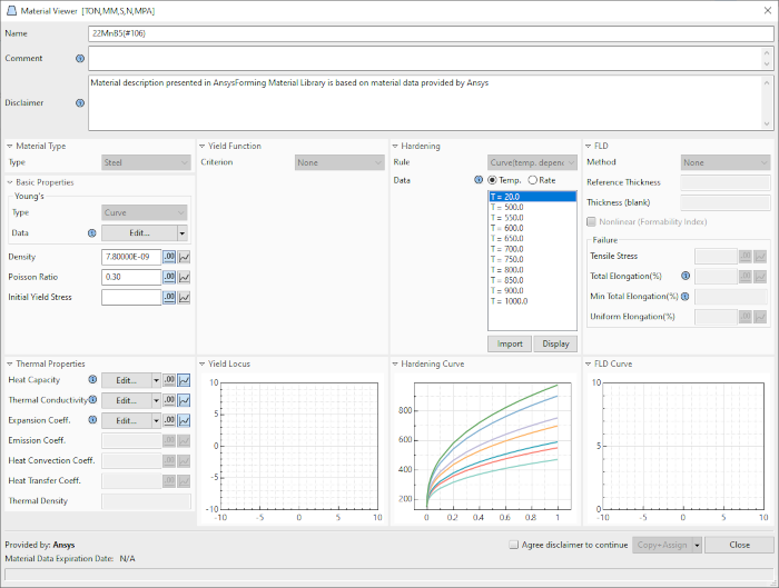
In thermal materials:
Yield Function Criterion is "None"
FLD Method is "None"
Hardening curves are temperature-linked and rate-related.
Thermal Properties are listed in the lower left section. Some thermal properties can be edited either by value or by using the curve editor. Use the buttons next to these fields to switch between the two modes.
Unsupported Material Models
Ansys Forming currently supports the following material models (as defined in the LS-DYNA Keyword Manual, Vol. II):
Cold Stamping
MAT_36, *MAT_3-PARAMETER_BARLAT_NLP
MAT_37, *MAT_TRANSVERSELY_ANISOTROPIC_ELASTIC_PLASTIC_NLP2
MAT_39, *MAT_FLD_TRANSVERSELY_ANISOTROPIC
MAT_122, *MAT_HILL_3R
MAT_125, *MAT_KINEMATIC_HARDENING_TRANSVERSELY_ANISOTROPIC_NLP
MAT_133, *MAT_BARLAT_YLD2000
MAT_136, *MAT_VEGTER_STANDARD
MAT_226, *MAT_KINEMATIC_HARDENING_BARLAT89_NLP
MAT_242, *MAT_KINEMATIC_HARDENING_BARLAT2000
MAT_320, *MAT_GENERAL_YIELD
Hot Forming
MAT_106, *MAT_ELASTIC_VISCOPLASTIC_THERMAL
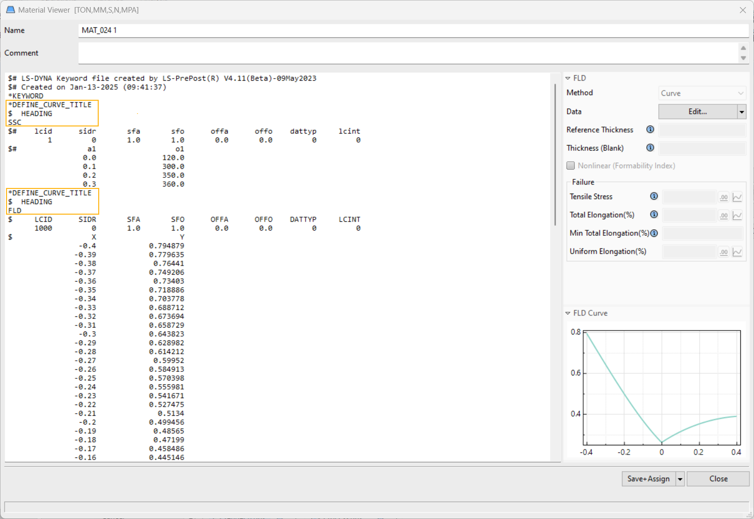
If you import an unsupported material model, the application cannot display the material properties as shown in Figure 3.13 and Figure 3.15.Instead, the Material Viewer displays the material card with LS-DYNA keywords.
Review the material card and edit as needed to ensure accuracy and verify that identifiers are unique. The application automatically replaces the Material ID (mid) to prevent conflicts.
To display hardening and FLD curve in the Material Viewer, define them using the following sample structure. Use the keyword title SSC (stress-strain curve) for the hardening curve (SSC is used to calculate the n-value when you select the Keeler method for FLD), and use FLD or FLC for the FLD curve.
Note: Because FLD is dependent on SCC, you cannot edit FLD information when initially importing the material. After you save the material, you can then open it again to edit the FLD information.
Note: Limitations for unsupported material models include:
You cannot change the data format of the keyword field.
You must maintain the order of keywords in the material card.
The assignable ID range for non-material keywords should be 1-4999.