


While in Fluent's meshing mode, the graphical interface is similar to the Fluent
solver's web-based interface with a singular window that includes a Main Menu ( ), visualization toolbar arcs, console window
access, and a stage navigator. For more information about the general elements of the
interface, see Using Ansys Fluent's Web Interface.
), visualization toolbar arcs, console window
access, and a stage navigator. For more information about the general elements of the
interface, see Using Ansys Fluent's Web Interface.

A new meshing workflow can be created, or an existing workflow can be opened, using the workflow drop-down menu and the corresponding tools in the upper left, similar to that described in The Workflow Tab.
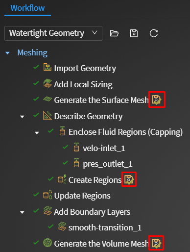
Just as in the desktop version of Fluent Meshing, many tasks contain a Display button that can appear alongside the task name when you hover over the task in the workflow. This will allow you to view the current state of the mesh at a specific task.
This button is available for any supported up-to-date task, however, it will not appear for any unsupported tasks or for the Run Custom Journal task.
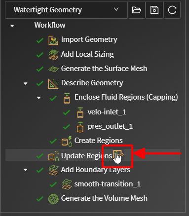
Similar to the desktop version of Fluent Meshing, several tasks contain an additional button that can appear alongside the task name in the workflow. This will allow you to toggle on or off the ability to save task editing files so the task can be more quickly restored to a previous state.
Tasks that currently save task-specific files will use this icon (
 ), whereas tasks that currently do not
save task-specific files will use this icon (
), whereas tasks that currently do not
save task-specific files will use this icon ( ) upon hovering over the task
name.
) upon hovering over the task
name.The View Arc is a circular toolbar located in the lower left-hand side of the window and is similar to that found in the Fluent web-based interface, described in The View Arc.
While in meshing mode (that is, within the Meshing "stage"), the Results Arc is a circular toolbar located in the lower right-hand side of the window that contains useful tools that are specific to working with meshes. You can use this to visualize meshing elements and to perform mesh checks and evaluate mesh quality.
Clipping Plane: lets you control the visibility and positioning of the clipping plane, as well as the cell layer obtained from it.

Display Options: lets you control the visibility of the edges and faces, highlighting and transparency in the geometry.

Perform Mesh Check: displays mesh check results to the console.
See Performing a Mesh Check and Diagnostics for more information about using this tool.
Evaluate Surface Quality and Evaluate Volume Quality: allows you to display surface and volume mesh quality results to the console.

See Diagnosing the Mesh Quality for more information about using this tool.
Diagnostic Tools: allows you to perform a detailed analysis of your mesh.

See Using the Diagnostics Tools Dialog Box for more information about using this tool.
Bounds: allows you to limit the display to within a specified distance of a selected entity. Select an entity (node, edge, face, zone) and specify a Delta value. The Set Ranges and Reset buttons affect all directions simultaneously, or enable and disable the directions individually. The Delta value can be adjusted using the Up and Down arrow keyboard shortcuts if desired.

Note: Your settings in the Clipping Plane tool also work in conjunction with specified ranges in the Bounds tool, such that your bounds selections and range settings are respected when interacting with the clipping plane.
See Generating the Mesh Display using Onscreen Tools for more information.
Note that while using the workflow, you can hide and show any selected surface(s) by using the context menu within the graphics window.
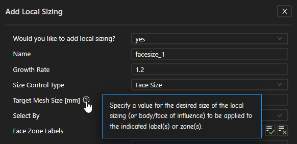
Throughout the various tasks of the workflow, field-level user assistance provides guidance and information for a selected field.
Fluent Meshing desktop-specific preferences for the workflows are available from the Main menu (
>Desktop
Preferences...). 
See Setting Preferences for Workflows for more details on each item.
Fluent web interface-specific preferences are also available from the Main menu (
>Web
Preferences...). Here, you can control preferences such as the
Theme (light or dark), logo display, large model support, the ability
to allow editing of unsupported tasks, or the ability to show the mesh on
connection.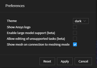
Fluent Meshing-specific shortcuts are available from the Main menu (
>Shortcuts...). 
In this panel, commonly-used shortcuts are available when working with your meshing workflow. There are several that are indicated by an informational icon (
 ), which designates shortcuts
that require you to enable the Override browser shortcuts checkbox
for them to work.
), which designates shortcuts
that require you to enable the Override browser shortcuts checkbox
for them to work.Just as in the Watertight Geometry workflow of the desktop version of Fluent Meshing, there are several tasks that employ the use of lists and can often contain a large number of items to choose from. For many such lists, you can use the Filter option to provide text and/or expressions in filtering the list. Alternatively, you can use the Select option to provide text and wildcard expressions to filter the list and to automatically select those items that satisfy the wildcard conditions.
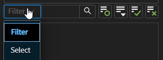
See Filtering Lists and Using Wildcards for more information.
Just as in the Watertight Geometry workflow of the desktop version of Fluent Meshing, there are a few tasks (such as the Update Boundaries task or the Update Regions task for example) that employ the use of tables that allow you to perform various operations on one or more selected items at once using the context menu.
For instance, once you select one or more boundaries in the table of the Update Boundaries task:
Use the Draw Selections option to easily display the selected boundaries in the graphics window.
Use the Set Boundary Label option to easily change the label for all selected boundaries.
Use the Set Boundary Type option to easily change the type for all selected boundaries.

See Updating Boundaries or Updating Regions for more information.
You can choose a specific color for any selected object(s) in the graphics window by using the Color by > Uniform color option from the context menu. Use the Esc key to release any selection(s) in the graphics window. Subsequently, you can randomize the colors of unselected objects displayed in the graphics window using Color by > Randomize colors option from the context menu.

Important: Once you have a volume mesh, you can create a fluid flow simulation directly in Fluent's web interface by choosing the Switch to Solution option in the Main menu (in the upper left hand corner), or by clicking the arrow to the right in the stage navigator at the bottom center of the screen. Using the Switch to Solution option allows you to set up your simulation, however, you will be unable to return to the meshing workflow.