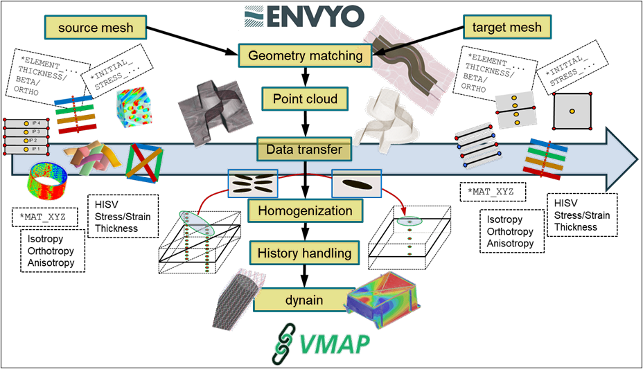
Figure 1.3: Envyo® Flow Chart shows the general structure of the Envyo program. Its workflow begins with a command file, often referred to as a mapping.in file, which is read by the executable. Then, the program reads the listed source and target files and, if necessary, performs specific geometry matching operations and unit system conversions to ensure the geometries are aligned for the data transfer. The source file can be an LS-DYNA simulation result file containing stresses, strains, and history variables such as a dynain file or simulation results from third party tools (Moldflow, Moldex3D, Theseus-FE, etc.). The target mesh is generally an LS-DYNA mesh that will be used for a subsequent analysis.
Next, the Envyo® program assigns the stored information from the source to point clouds generated based on the location of the information storage (nodes, integration points, or element centers). Then, the program transfers the data using the available mapping routines. The available options can be a simple nearest neighbor search, native finite element projection method, averaging method based on distance weighting factors, and so on. If required, the Envyo® program can homogenize the transferred parameters in a subsequent step such as:
Calculating average orientations after a fiber orientation transfer.
Estimating the resulting stiffness properties for short fiber reinforced plastic (SFRP) properties.
Introducing locally varying degrees of cure for adhesives.
You can edit the history variables with user-defined equations before the program writes the result data to a dynain or VMAP file.
For feedback regarding possible workflows or your specific needs, you may contact envyo@ansys.com.