To add a three-dimensional internal fan condition to a body that represents the fan
location:
Click the Fluid Flow dropdown menu in the ribbon of the
Simulation tab and choose Internal Fan.
Select a single fluid body that represents the location of the fluid at the internal
fan.
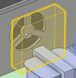
Note: You are not selecting the actual solid fan, but rather a
volumetric fluid body that you create, which is representative of the fan region. The
internal fan region is only an approximation of the actual flow, so it can be any
shape with constant cross section that represents the fan region where the flow enters
and exits.
Here is an example of a rectangular volumetric fluid body representing the location at
the internal fan.
The application automatically detects the inlet face of the fan.
If your model contains named selections, click Advanced filters
and use Link named selections to choose one from the list.
To override the automatic selection of inlet face, use the Select inlet face tool guide
to
define the inlet of the fan.
Note: The inlet and outlet of the fan must be located on single
faces that span the entire cross section of the body. The inlet and outlet faces of the
fan cannot be external.
Define the pressure rise due to the fan.
In the HUD's options panel, two methods are available:
In the options panel, Shrouded is selected by default. A
shrouded fan channels fluid through the fan so that the fluid is pulled through the fan
system. Creating a shrouded fan creates internal fluid walls on the exterior faces of the
fan, which force the fluid to flow through the fan. This maximizes the cooling efficiency
of the fan.
With this option off, it creates a fluid-fluid interface between the fan fluid volume
and the surrounding fluid volume, allowing fluid to flow through the interface.
In the options panel, you can include a heat source, select Specify total
heat. Enter the total heat value representing the heat dissipation of the
fan.
In the options panel,
specify the Hub radius and Tip radius of the
blade. This value will not affect the fluid flow and will only be used for fan curve
filtering.
Click Accept.
Note:
Flow inlets and outlets cannot be located on the fan body.
If the simulation is transferred to the Fluent application, it will not include internal fan data.
Internal fans are not supported in Refine when LiveGX is
switched off. Turn on Use LiveGX solver under
Simulation Options, or switch to the
Explore stage.


 and use Link named selections
  to choose one from the list.
 to
define the inlet of the fan.
Note: The inlet and outlet of the fan must be located on single faces that span the entire cross section of the body. The inlet and outlet faces of the fan cannot be external.
to
define the inlet of the fan.
Note: The inlet and outlet of the fan must be located on single faces that span the entire cross section of the body. The inlet and outlet faces of the fan cannot be external.