


(Part A) Create a basic motion setup using Rocky’s built-in tools to define geometry movement through CSV-based Motion Time Series. This section highlights the limitations of this method when dealing with complex or interdependent motions, setting the stage for the advantages of using Ansys Motion in the next steps.
(Part B) Set up 2-Way Coupling abilities between Rocky and Ansys Motion, and then use Ansys Motion to export pre-defined geometry movements into a Functional Mock-Up Unit (FMU) file.
(Part C) Use the FMU information exported earlier out of Ansys Motion to set up and process the 2-Way Coupled simulation in Rocky.
To illustrate the advantages of coupling Rocky with Ansys Motion, we will first create a simple motion setup using Rocky's built-in motion tools. In this example, we will define basic geometry movements by importing pre-defined motion profiles from .csv files through Rocky Motion Frames Time Series feature. Although functional, you will notice that this approach quickly becomes complex and impractical when dealing with highly coordinated or intricate movements, highlighting the benefits of using the Ansys Motion coupling method discussed later Part B.
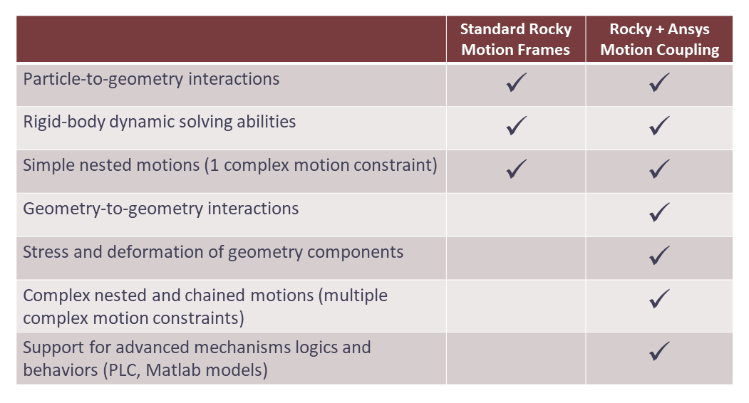
The primary benefits of 2-Way Coupling Rocky with Ansys Motion as compared to using the standard Rocky Motion Frames method are explained in the table below.
Important: This ADVANCED tutorial assumes that you are already familiar the following programs and resources:
The Rocky program.
If this is not the case, it is recommended that you complete at least Tutorials 01 - 05 before beginning this tutorial.
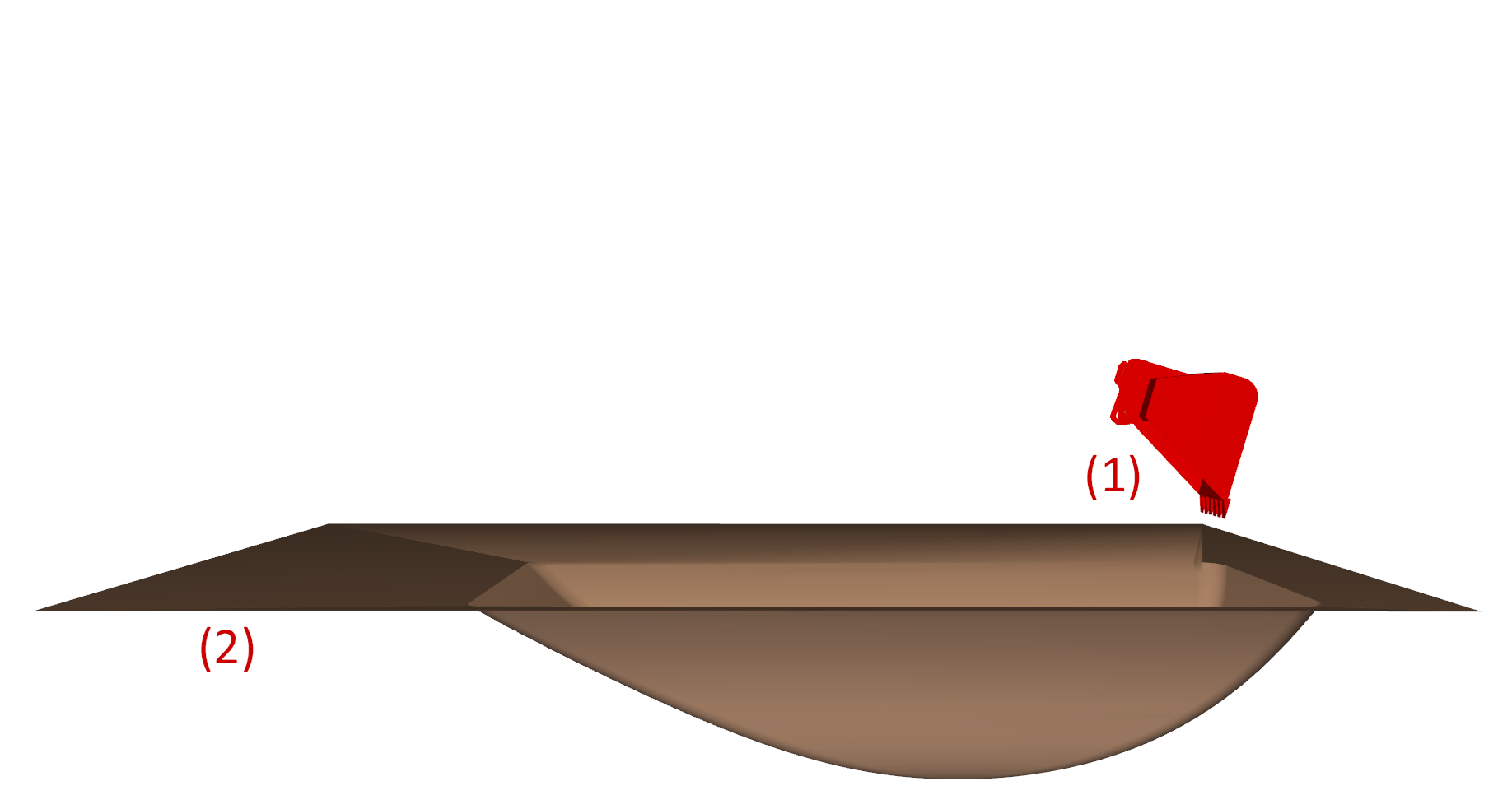
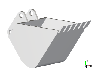
For simplicity, this basic setup will consider only the geometries Bucket.stl and Ground.stl:
(1) Bucket
(2) Ground and pit
To begin the steps for this tutorial, do the following:
Download the
dem_tut19_files.zipfile here .Unzip
dem_tut19_files.zipto your working directory.Open Rocky 2025 R2.
Create a new project.
Save the empty project to a location of your choosing.
Use the information in the table that follows to start setting up your Rocky project.
Tip: If you run into settings or procedures in these tables that you are not yet familiar with, please refer to the Rocky User Manual and/or other Tutorials (via the Introductory Tutorials and Advanced Tutorials) to find the detailed instructions you need.
Step Data Entity Editors Location Parameter or Action Settings A Study Study Study Name Backhoe Loader B Physics Physics | Momentum Rolling Resistance Model Type C: Linear Spring Rolling Limit ⯆ Numerical Softening Factor 0.1 [ - ]
For the Geometries step, we will import the .
Use the information in the table that follows to continue setting up your Rocky project.
Step Data Entity Editors Location Parameter or Action Settings A Geometries Import Wall Bucket.stl with "m" for Import Unit B Geometries ﹂Bucket
Wall | Transform Triangle Size 0.05 [m] C Geometries Import Wall Ground.stl with "mm" for Import Unit
For the Materials step, we will:
Modify the Default Particles material.
Create a new material representing the Ground based on the Default Boundary Material.
Use the Default Boundary Material for the Bucket geometry.
Note: The values for this last Material will be left as default.
Use the information in the table that follows to continue setting up your Rocky project.
Step Data Entity Editors Location Parameter or Action Settings A Materials ﹂Default Particles
Material Bulk Density 1500 [kg/m3] B Materials ﹂Default Boundary
Duplicate Material C Materials ﹂Default Boundary <01>
Material Name Ground D Geometries ﹂Ground
Wall Material Ground ⯆ E Materials Interactions … | Default Particles ⯆ Ground ⯆
Static Friction 1 [ - ] Dynamic Friction 1 [ - ] … | Default Particles ⯆ Default Particles ⯆
Static Friction 1 [ - ] Dynamic Friction 1 [ - ]
Use the information in the following table to set up the Bucket Motion Frame for this tutorial:
Step Data Entity Editors Location Parameter or Action Settings A Motion Frames Create Motion Frame B Motion Frames ﹂Frame <01>
Frame Name Bucket Motion Relative Position -3, 1, -5 [m] Add Motion Type Time Series Rotation⯆ Load File bucket_sum_ang-velocity.csv Add Motion Type Time Series Translation⯆ Load File bucket_sum_dis-velocity.csv
Once the Motion Frame is created, it can be assigned to the respective geometry.
| Step | Data Entity | Editors Location | Parameter or Action | Settings |
|---|---|---|---|---|
| C | Geometries ﹂Bucket | Wall | Motion Frame | Bucket Motion⯆ |
For the Particles step, we will create a sphere-shaped particle group with some added rolling resistance.
For the Inlets and Outlets step, we will create a Particle Custom Inlet and import a .csv file that defines an already-filled pit of particles.
Note: There is no need to set the particle size here because it will be defined in the Custom Inlet file.
Use the information in the table that follows to finish setting up your Rocky project.
Step Data Entity Editors Location Parameter or Action Settings A Particles Create Particle B Particles ﹂Particle <01>
Particle | Movement Rolling Resistance 0.35 [ - ] C Inlets and Outlets Create Particle Custom Inlet D Inlets and Outlets ﹂Particle Custom Inlet <01>
Particle Custom Inlet Particle Particle <01> Load File Select file to import custom_input_sphere.csv E Solver Solver | Time Simulation Duration 10 [s] Solver | General Simulation Target CPU ⯆
Ensure that your Ansys license is active.
From the Solver entity, click Start.
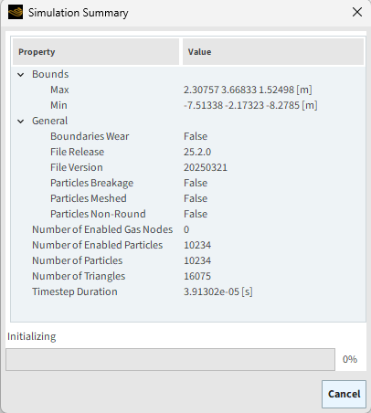
The Simulation Summary screen appears (as shown), then processing begins.
Important: Do not press Stop or lose access to your Ansys license while the simulation is processing. You might not be able to Resume the coupled simulation once it is stopped.
We used Rocky’s built-in motion tools to create a simple geometry motion using CSV-based Motion Time Series.
During this tutorial, it was possible to:
Import and configure basic geometries
Define and assign motion data using time series files
Set up particle properties and simulate a simple digging motion
While functional, this approach highlighted the challenges of manually controlling complex, multi-body motions.
What's Next? If you completed this part successfully, then you are ready to move on to Part B and set up and process the Rocky portion of this coupled simulation.
The main purpose of this tutorial is to set up 2-Way Coupling abilities between Rocky and Ansys Motion.
We will then use Ansys Motion to export pre-defined geometry movements into a Functional Mock-Up Unit (FMU) file that will later be coupled with Rocky.
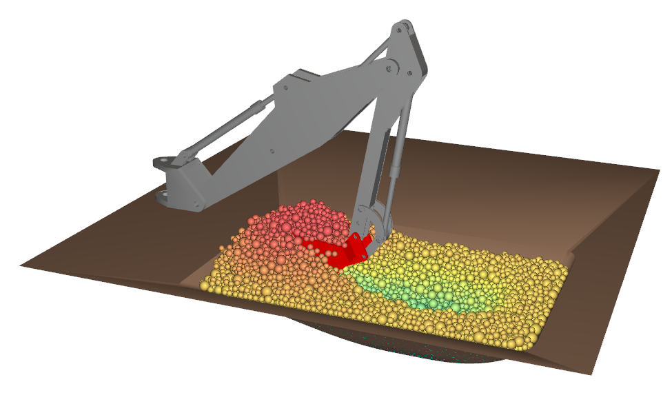
The scenario considered in this tutorial is evaluating the performance of a backhoe loader's bucket as it scoops material out of a pit in the ground.
In Part A of this tutorial, you will learn how to:
Download and install the Ansys Motion Coupling module
Open an existing Subsystem file in Ansys Motion
Export the motion FMU file out of Ansys Motion
Later in Part C you will learn how to import the FMU file into Rocky, and run the 2-Way coupled simulation.
To complete this tutorial, you are required to have on a Windows machine both of the following programs:
Ansys Motion 2025 R2.
Important: Ansys Motion must be installed in the same installation folder as your other Ansys 2025 R2 products.
Rocky 2025 R2.
Tip: If you are unsure which version of Rocky you have, you can view the Version information on the About Rocky screen. (From the Rocky Help menu, click About.)
Important: This ADVANCED tutorial assumes that you are already familiar the following programs and resources:
The Rocky program.
If this is not the case, it is recommended that you complete at least Tutorials 01 - 05 before beginning this tutorial.
The Ansys Motion program.
If that is not the case, please refer to the Ansys Motion user documentation for basic introduction about Motion usage before beginning this tutorial.
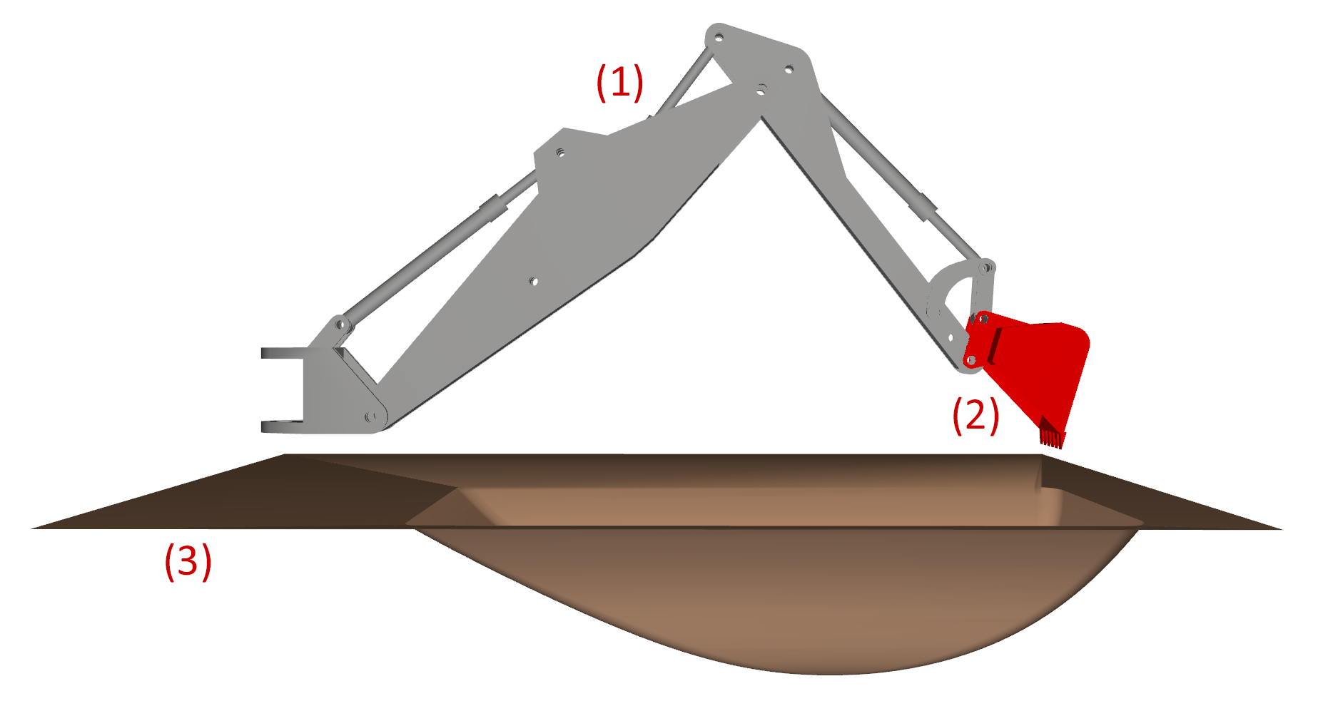
The geometries in this tutorial are composed of:
(1) Boom, Arm, and Actuators (several components)
(2) Bucket
(3) Ground and pit
Note: The first two sets of geometries are included in the Ansys Motion setup file. The third geometry is provided as an .stl file that will be imported into Rocky later.
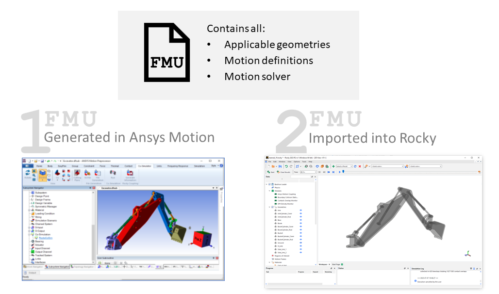
Ansys Motion Coupling enables you to use motions defined in Ansys Motion within the DEM simulation you set up and run in Rocky.
Motions are exported into an "all-in-one" Functional Mock-Up Unit (FMU) file.
This FMU is then imported into Rocky, defining both geometries and motions.
Exporting and importing the FMU requires the installation of two modules' one for Ansys Motion and one for Rocky.
Both are bundled into one .exe file that is available on the Ansys Customer Portal.
STEP 1: Download and install the Ansys Motion Coupling module.
Download the Ansys Rocky Installation Guide document and go to the Ansys Rocky Integrations section to better understand the installation of the coupling with the Motion. You can find the document on the link from the Ansys Customer Portal: https://download.ansys.com/Installation%20and%20Licensing%20Help%20and%20Tutorials. .
Download the Additional Package for Rocky and extract the content from ansys-rocky-motion-coupling-bin-25.2.0-win64.exe file.
Tip: We will not cover these additional resources in this tutorial but you can use them to learn more about Ansys Motion Coupling with Rocky.
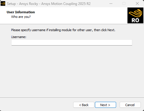
Open the .exe, and then follow the steps in the wizard, ensuring the following:
When you get to the User Information screen, do one of the following:
If you are installing this module for someone else, enter their Windows Username in the field provided.
Tip: This step should only be necessary if you are logged in as an administrator and the user for which you are installing the module does not have the proper installation permissions.
Otherwise, if you are installing this module for yourself, you can leave the Username field blank.
When you get to the Select Components screen, select both components listed (as shown).

On the Select Additional Tasks, enable the Ansys Motion 2025 R2 Module checkbox. Also enable the checkbox for Mechanical (optional).

Follow the remaining steps in the wizard to complete the installation.
STEP 2: Open the Ansys Motion project you want to couple with Rocky.
Download the
dem_tut19_files.zipfile here .Unzip
dem_tut19_files.zipto your working directory.Open Motion Pre 2025 R2.
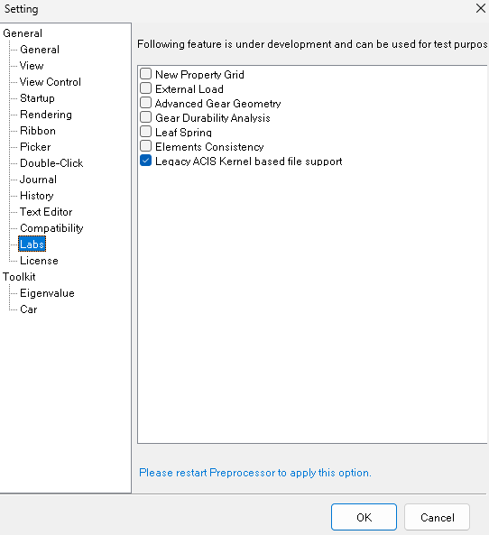
From the File menu, click the Setting button, go to Labs tab and enable the Legacy ACIS Kernel based file support checkbox.
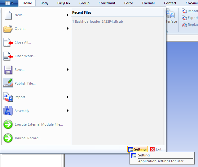
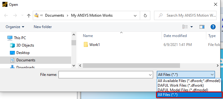
From the File, menu, click Open.
From the Open dialog, from the All Available Files list, select All Files (as shown).
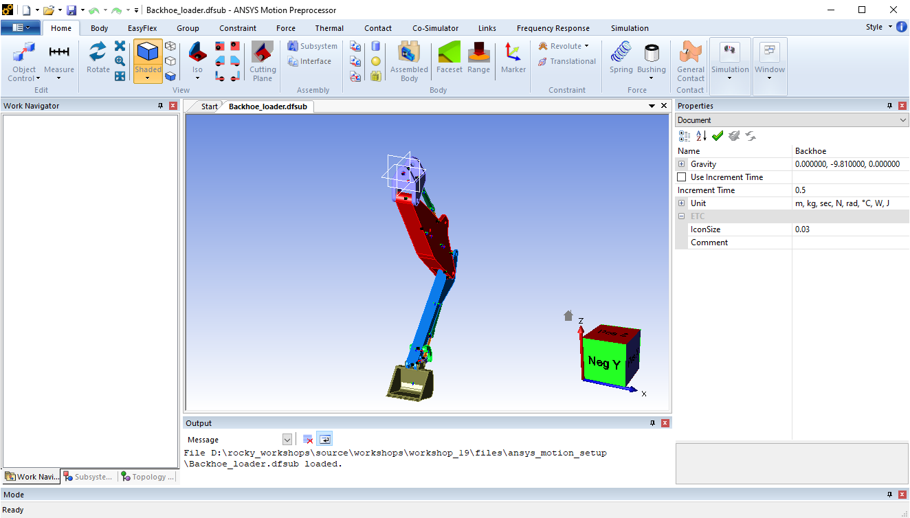
From the Open dialog, locate the ansys_motion_setup folder inside the dem_tut19_files folder you downloaded, select the subsystem file Backhoe_loader.dfsub, and then click Open.
The backhoe loader model appears in the view (as shown).
For Ansys Motion Coupling to work, we need to ensure that the gravity direction exactly matches what we will use in Rocky.
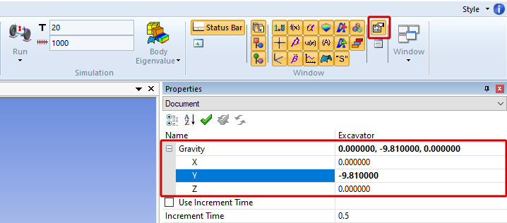
To verify that gravity is set in the Y direction, do the following:
From the Properties panel, view the values for Gravity (as shown).
Tip: To view this panel, from the main Home tab on the Window toolbar, click the Properties button.
We also must ensure that the simulation time in Ansys Motion is equal to or greater than the one we will use in Rocky.
Tip: Because a stopped Ansys Motion Coupling simulation might not be able to be resumed, extended, nor restarted in Rocky, it is recommended that you make the simulation time in Ansys Motion longer than what you think you need.
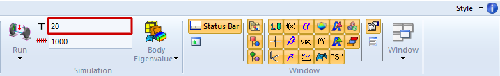
We plan to have a 12s simulation in Rocky. Verify that the simulation time in Ansys Motion is greater than this by doing the following:
From the main toolbar, review the simulation time (T) value (as shown).
STEP 4: Export the files needed for Ansys Motion Coupling.
From the Co-Simulator tab, click the Generate Information button on the Rocky Coupling toolbar (as shown).

This version of Ansys Motion Coupling supports particle interactions on only rigid bodies without beam elements.
Flexible bodies without beam elements are supported on the Ansys Motion side but will not interact with particles in Rocky.
Note: Choosing to include flexible bodies in your coupled simulation will increase processing time.
Part of the exporting files step is choosing how body components are treated during coupling. Specifically:
Bodies marked as Output will have their motions shared with Rocky.
Bodies marked as Input will collect forces and moments due to interactions with particles. This data will then be used by the Ansys Motion solver during processing.
For this tutorial, we want all bodies to have motions in Rocky, but only the Bucket body to collect particle forces.
From the Rocky Coupling dialog, do all the following (as shown):
From the Output column, enable the main checkbox to select all the bodies.
From the Input column, enable only the Bucket checkbox.
Click Export.
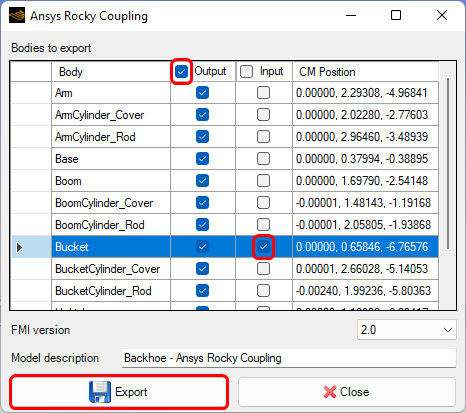
From the Save As dialog, enter the File name Backhoe_FMU, and then click Save.
The export can take several minutes. You will get a confirmation message when it completes.
Click OK to close the confirmation message, and then click Close to close the Rocky Coupling dialog.
Save your project and then close Ansys Motion.
This completes Part B of this tutorial.
For further information on Ansys Motion Coupling with Rocky, we suggest searching the Modules Manual. To access it, do the following:
From the top toolbar, under Help Menu, select Ready-to-use Modules .
Select Modules Manual and look for Chapter 2: Ansys Motion Coupling Module.
We used Ansys Motion to set up and export geometry movements that will later be coupled with Rocky.
During this tutorial, it was possible to:
Download and install the .exe file that contains the two Ansys Motion Coupling modules
Open an existing subsystem file and then verify that is ready for Rocky coupling
Generate and then export the motion FMU file out of Ansys Motion
What's Next? If you completed this part successfully, then you are ready to move on to Part C and set up and process the Rocky portion of this coupled simulation.
The purpose of this tutorial is to use the information we exported out of Ansys Motion in Part B to set up and process the 2-Way Coupled simulation in Rocky.
We will make use of the Functional Mock-Up Unit (FMU) file we created in Part B.
As a reminder, the scenario considered in this tutorial is the analysis of how well the bucket part of a backhoe loader holds up to its material load after scooping particles from a pit in the ground.
In Part B of this tutorial, you will learn how to:
Enable the Multibody Dynamics FMU Coupling module in Rocky
Use the FMU file to import both motions and geometries
Define a pre-filled particle bed with a custom input
Process and post-process the coupled simulation in Rocky
To complete this tutorial, you are required to have on a Windows machine both of the following programs:
Ansys Motion 2025 R2.
Important: Ansys Motion must be installed in the same installation folder as your other Ansys 2025 R2 products.
Rocky 2025 R2.
Tip: If you are unsure which version of Rocky you have, you can view the Version information on the About Rocky screen. (From the Rocky Help menu, click About.)
In addition, you must have already downloaded and installed the Ansys Motion Coupling module.
Tip: Refer to Part A of this tutorial for installation details.
Important: This ADVANCED tutorial contains fewer details, screenshots, and procedures than other Rocky tutorials.
If you do not already have a good level of familiarity with the most common setup and post-processing tasks in Rocky, it is recommended that you complete at least Tutorials 01 - 05 before beginning this one.

As a reminder, the geometries in this tutorial are composed of:
(1) Boom, Arm, and Actuators (several components)
(2) Bucket
(3) Ground and pit
Note: The first two sets of geometries are included in the Ansys Motion FMU file. The third geometry is provided as an .stl file. All will be imported into Rocky in this tutorial.
Whether or not you completed Part B of this tutorial, do the following:
Download the
dem_tut19_files.zipfile here .Unzip
dem_tut19_files.zipto your working directory.Open Rocky 2025 R2.
Create a new project.
Save the empty project to a location of your choosing.
Use the information in the table that follows to start setting up your Rocky project.
Tip: If you run into settings or procedures in these tables that you are not yet familiar with, please refer to the Rocky User Manual and/or other Tutorials (via the Introductory Tutorials and Advanced Tutorials) to find the detailed instructions you need.
Step Data Entity Editors Location Parameter or Action Settings A Study Study Study Name Backhoe Loader B Physics Physics | Momentum Rolling Resistance Model Type C: Linear Spring Rolling Limit ⯆ Numerical Softening Factor 0.1 [ - ]
For the Modules step, we will be enabling the Ansys Motion Coupling functionality and turning on the collection of boundary-related collision data.
Use the information in the table that follows to start setting up your modules.
Step Data Entity Editors Location Parameter or Action Settings A Modules Modules Multibody Dynamics FMU Coupling (Enabled) Boundary Collision Statistics (Enabled) B Modules ﹂Boundary Collision Statistics
Boundary Collision Statistics Stresses (Enabled)
Stresses: Rocky will collect the normal and tangential stress values measured by each individual geometry triangle. This can be useful for analyzing the distribution of load due to particle collisions on a geometry.
We will use the first module to import the FMU file we exported out of Ansys Motion in Part B. As a reminder:
A single FMU file contains all the geometries, motion definitions, and motion solver information Rocky needs for coupling.
We will use this same FMU file to import geometries in a separate step later.
Important: To avoid errors during geometry import later, an FMU file should NOT be manually renamed after it is generated.
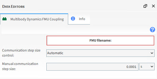
From the Data panel, under Modules, select Multibody Dynamics FMU Coupling.
From the Data Editors panel, do the following:
Leave the Communication step size control as Automatic. (For each Ansys Motion timestep, Rocky computes 100 timesteps.)
Click the FMU filename: button (as shown).
From the Select file to import dialog, do one of the following:
If you completed Part B, find and select the FMU file that you exported as part of that tutorial.
If you did not complete Part B, find the dem_tut19_files folder you downloaded, find the geometry folder, and then select the Backhoe_FMU.fmu file.
Click Open.
Once the Select file to import dialog closes without error, this indicates that the FMU file was successfully imported.
For the Geometries step, we will import the exact same FMU file that we used earlier.
Important: To ensure correct motions, use the same FMU file in both the Multibody Dynamics FMU Coupling module and for importing geometries.
Because we want to analyze particle forces on the Bucket component later, we must also refine its mesh.
And lastly, we'll import the ground and pit geometry as an .stl file.
Use the information in the table that follows to continue setting up your Rocky project.
Step Data Entity Editors Location Parameter or Action Settings A Geometries Import Wall Backhoe_FMU.fmu with "m" for Import Unit B Geometries ﹂Bucket
Wall | Transform Triangle Size 0.05 [m] C Geometries Import Wall Ground.stl with "mm" for Import Unit
For the Materials step, we will:
Modify the Default Particles material.
Create a new material representing the Ground based on the Default Boundary Material.
Use the Default Boundary Material for the excavator geometries.
Note: The values for this last Material will be left as default.
Use the information in the table that follows to continue setting up your Rocky project.
Step Data Entity Editors Location Parameter or Action Settings A Materials ﹂Default Particles
Material Bulk Density 1500 [kg/m3] B Materials ﹂Default Boundary
Duplicate Material C Materials ﹂Default Boundary <01>
Material Name Ground D Geometries ﹂Ground
Wall Material Ground ⯆ E Materials Interactions … | Default Particles ⯆ Ground ⯆
Static Friction 1 [ - ] Dynamic Friction 1 [ - ] … | Default Particles ⯆ Default Particles ⯆
Static Friction 1 [ - ] Dynamic Friction 1 [ - ]
For the Particles step, we will create a sphere-shaped particle group with some added rolling resistance.
For the Inlets and Outlets step, we will create a Particle Custom Inlet and import a .csv file that defines an already-filled pit of particles.
Note: There is no need to set the particle size here because it will be defined in the Custom Inlet file.
Use the information in the table that follows to finish setting up your Rocky project.
Step Data Entity Editors Location Parameter or Action Settings A Particles Create Particle B Particles ﹂Particle <01>
Particle | Movement Rolling Resistance 0.35 [ - ] C Inlets and Outlets Create Particle Custom Inlet D Inlets and Outlets ﹂Particle Custom Inlet <01>
Particle Custom Inlet Particle Particle <01> Load File Select file to import custom_input_sphere.csv E Solver Solver | Time Simulation Duration 12 [s] Solver | General Simulation Target CPU ⯆
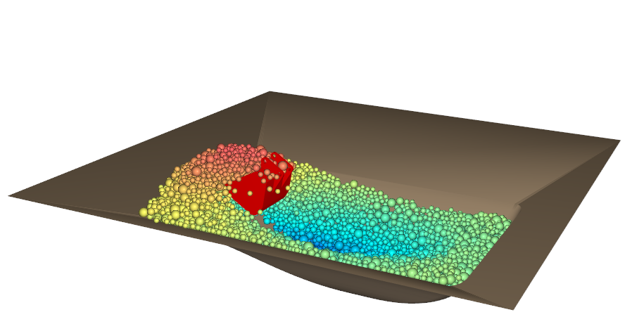
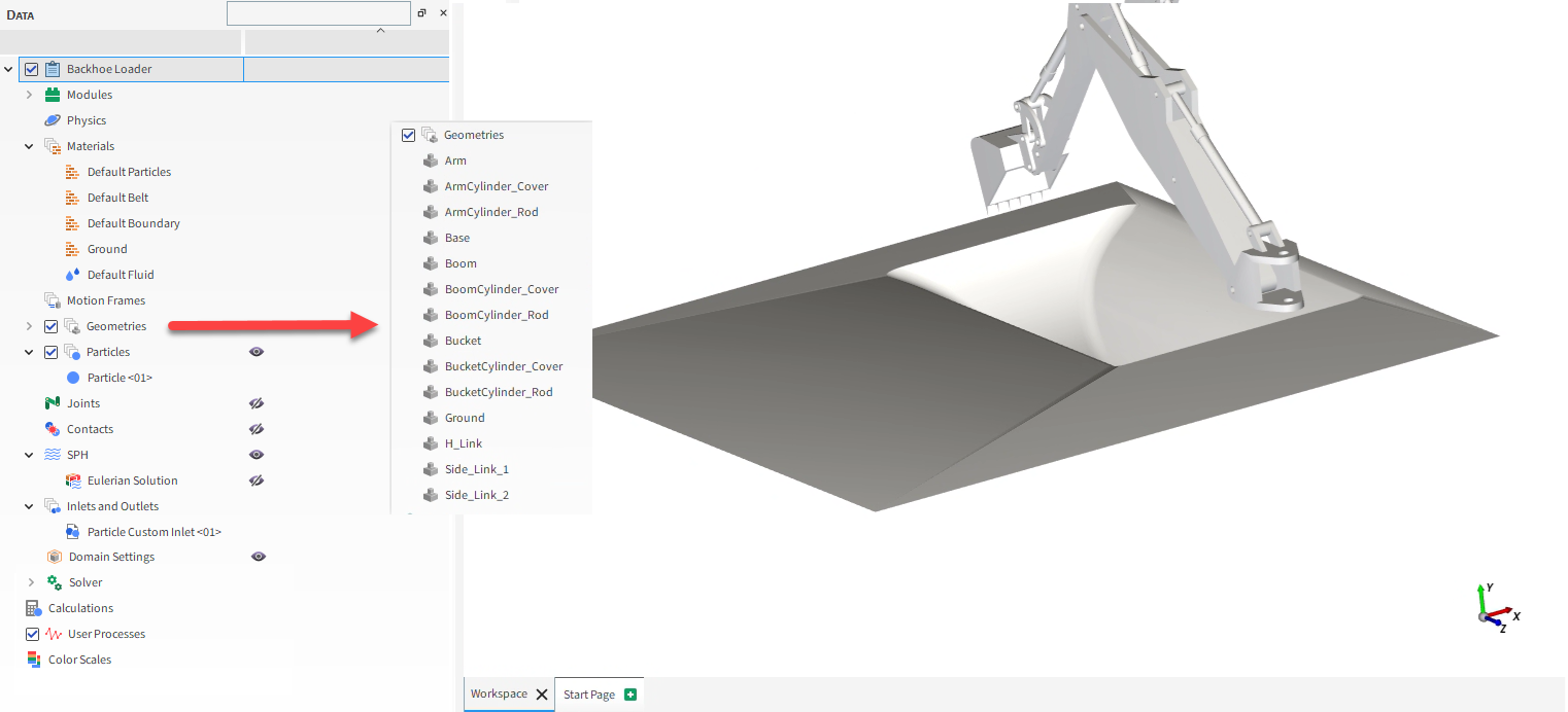
With a 3D View window opened, your Data panel and Workspace should look similar to the below image.
Ensure that your Ansys license is active.
From the Solver entity, click Start.
The Simulation Summary screen appears (as shown), then processing begins.
Important: Do not press Stop or lose access to your Ansys license while the simulation is processing. You might not be able to Resume the coupled simulation once it is stopped.
After processing is complete, we can analyze the particle forces on the bucket component.
For example, we can plot the Instantaneous Force in the Y direction:
From the Data panel, under Geometries, select Bucket.
From the Data Editors panel, select the Curves tab, right-click Force : Y : Instantaneous, and then click Show Curve in new Plot.
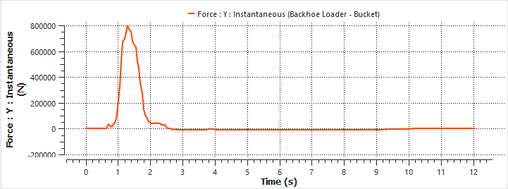
Results show the reaction force of the particles over the bucket surface during the ground digging phase (1-3 s) and the weight of the scooped material until the unloading phase (3-10 s).
Let's next evaluate the draw efficiency of the bucket by using a Cube User Process and a Time Plot to analyze the carried Particle Mass.
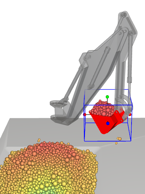
From the Time toolbar, choose a time when the bucket is full and the material is relatively stable. (For example, at [160] 8 s.)
Use the information in the table below to create the Cube.
Step Data Entity Editors Location Parameter or Action Settings A Particles Create a Cube User Process B User Processes ﹂Cube <01>
Cube Center -2.2, 0.7, -1.2 [m] Magnitude 1.8, 1.5, 1.7 [m]
This results in a Cube (blue outline, as shown) encompassing the full bucket.
Now, let's use Output variables to view the max value at 8 s.
Use the information in the table below to create and modify the output variable.
Step Item Location Parameter or Action Settings A Tools (menu) Show Expressions/Variables B Expressions/Variables Select Output tab C User Processes ﹂Cube <01>
Properties | Particle Mass Drag and drop to Output tab D Expressions/Variables Output | Particle_Mass Edit (button) E Edit Properties (dialog box) Property to Curve sum ⯆ Domain Range Specific Time ⯆ At Time 8 [s]
The updated value shows that the Particle Mass in the Bucket reaches about 750 kg before it is dumped.
Note: Your values might differ slightly from this tutorial.
You can also visualize stresses on the Bucket geometry in a 3D View window:
From the Window menu, click New 3D View.
From the Data panel, under Geometries, multi-select all components except for the Bucket component, and then click the eye icon to hide all but the bucket from the view (as shown).
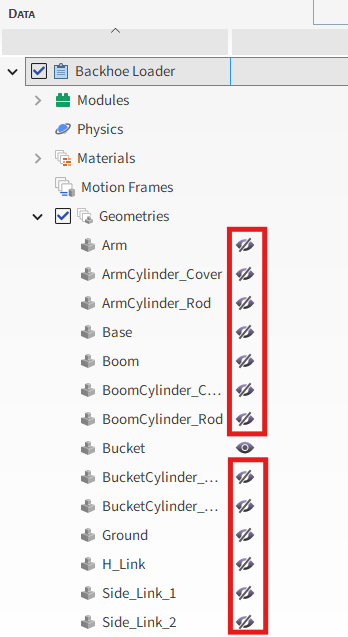
Repeat this process to hide the main Particles entity.
Only the Bucket geometry should be visible now (as shown).
From the Data panel, select the Bucket component.
From the Data Editors panel, select the Properties tab, and then click and drag Stress : Tangential to the 3D View window.
Use the Time slider to change the output when the bucket is actively scooping (for example, 3 s, as shown).
Adjust the limit of the color scale to optimize the mapping (for example, from 0 to 10000 Pa, as shown).
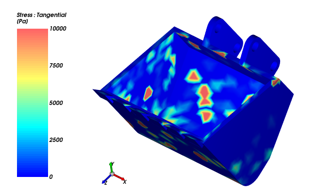
This analysis shows the shear stress caused by the interactions between particles and the bucket geometry, and therefore identifies zones that are prone to wear.
Extension: You can extend this analysis even farther by creating a Time Statistics Property on the Bucket and then plotting a contour of wear.
This completes Part C of this tutorial.
For further information on Ansys Motion Coupling with Rocky, we suggest searching the Modules Manual. To access it, do the following:
From the top toolbar, under Help Menu, select Ready-to-use Modules .
Select Modules Manual and look for Chapter 2: Ansys Motion Coupling Module.
Rocky was used to set up, process, and post-process a simulation of a backhoe loader with movements defined in Ansys Motion.
During this tutorial, it was possible to:
Enable the Multibody Dynamics FMU Coupling module in Rocky
Use the FMU file we created in Part A to import both motions information and geometries
Define a pre-filled particle bed by using a custom input .csv file
Process and post-process the coupled simulation in Rocky
What's Next? If you completed this tutorial successfully, then you are ready to move on to next tutorial.