


Important: Note that beta features have not been fully tested and validated. Ansys, Inc. makes no commitment to resolve defects reported against these prototype features. However, your feedback will help us improve the overall quality of the product. We will not guarantee that the projects using this beta feature will run successfully when the feature is finally released so you may, therefore, need to modify the projects.
This module enables you to set elastic, plastic and discrete breakage parameters for each joint of a custom fiber. This is quite useful when the goal is to represent heterogeneous particles that can be defined as complex fibers, such as plants.
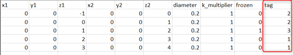
To use this module you need to define Tag values for each element of a custom fiber on the definition file (Figure 15.1: Tag column on the custom fiber definition file.).
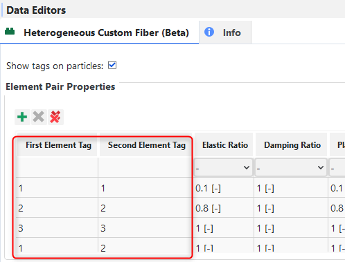
Then, the properties for each pair of tag values are defined on the module (Figure 15.2: Pairs of Tags table).
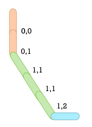
The information of the custom fiber definition file and the pairs of tags table is mapped to the joints of custom fiber, as shown in Figure 15.3: Tags mapped to joints. Thus, the elastic, plastic and discrete breakage models can be applied per joint.
The module uses the Bilinear Elastoplastic model for elastic and plastic behavior of the joints and the Tensile or Shear Stress for joint breakage model. Both already present in Rocky for homogeneous fiber modeling.
For the module to work with the Custom fiber definition file, all the Tag values must be positive values, as shown in Figure 15.1: Tag column on the custom fiber definition file..
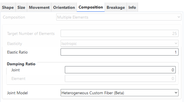
This module overwrites the original Rocky’s Elastic Ratio and the Joint Damping Ratio, shown on the Figure 4 Figure 15.4: Elastic Ratio and Joint Damping Ratio., but does not support overwriting the Element Damping ratio shown on the Figure 5 Figure 15.5: Element Damping Ratio.. Therefore, if element damping is needed, the same element damping ratio will be used for the whole particle.
If the element damping is enabled in the simulation, although the Rocky’s original Elastic Ratio is not used in the calculations of joints forces, moments and breakage criterion calculations, this parameter is used in the fundamental frequency calculation, which is, in its turn, used on the element damping coefficient calculation.
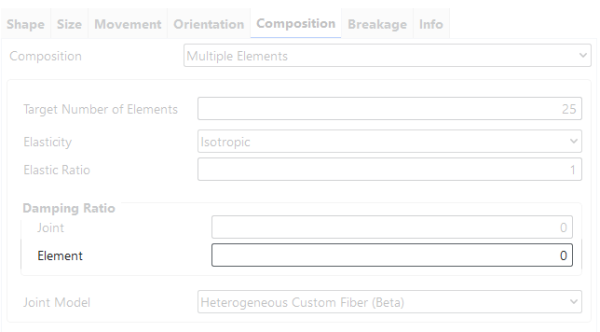
This module has several parameters that you can set, which are defined below and shown in Figure 15.6: Options for the Heterogeneous Custom Fiber (Beta) module. and Figure 15.7: Options for the Heterogeneous Custom Fiber (Beta) module..
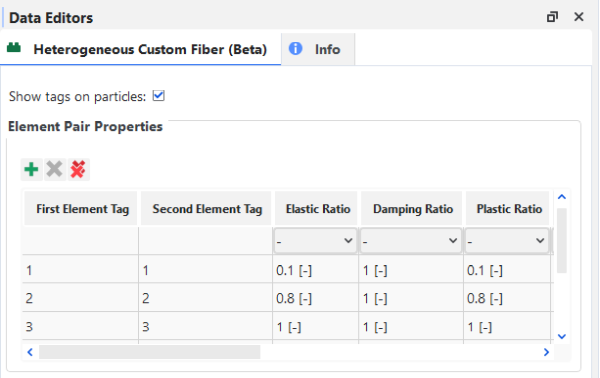
Show tags on particles: Defines whether tags given in the Custom Fiber Definition File will be saved as particle properties for post-processing.
Range: [Automatically provided.]
First Element Tag: Sets the first tag value that defines a pair of tags.
Range: [Positive Integer Values]
Second Element Tag: Sets the second tag value that defines a pair of tags.
Range: [Positive Integer Values]
Elastic Ratio: Defines the Elastic Ratio of a joint formed by elements with tag values defined by the First Element Tag and Second Element Tag values.
Range: [Positive Real Values]
Damping Ratio: Defines the Joint Damping Ratio of a joint that is formed by elements with tag values defined by the First Element Tag and Second Element Tag values. This value is not used for element damping.
Range: [Positive Real Values]
Plastic Ratio: Defines the Plastic Ratio of a joint formed by elements with tag values defined by the First Element Tag and Second Element Tag values.
Range: [Positive Real Values]
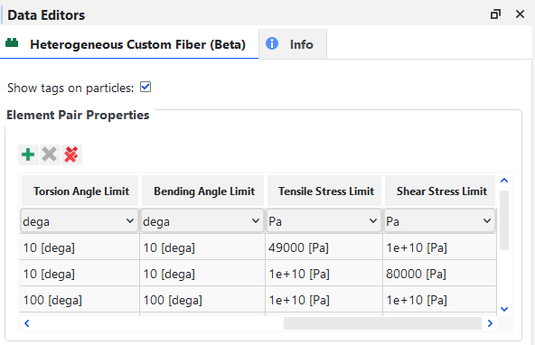
Torsion Angle Limit: Defines the Torsion Angle Limit of a joint formed by elements with tag values defined by the First Element Tag and Second Element Tag values.
Range: [Positive Real Values]
Bending Angle Limit: Defines the Bending Angle Limit of a joint formed by elements with tag values defined by the First Element Tag and Second Element Tag values.
Range: [Positive Real Values]
Tensile Stress Limit: Defines the Tensile Stress Limit of a joint formed by elements with tag values defined by the First Element Tag and Second Element Tag values.
Range: [Positive Real Values]
Shear Stress Limit: Defines the Shear Stress Limit of a joint formed by elements with tag values defined by the First Element Tag and Second Element Tag values.
Range: [Positive Real Values]
After processing your simulation, you can analyze the results using the same particle-related properties that are available by default in Rocky.
In addition, one extra particle property is available as shown in Figure 15.8: —Additional particle properties created by the Heterogeneous Custom Fiber (Beta) module. and explained below.
Figure 15.8: —Additional particle properties created by the Heterogeneous Custom Fiber (Beta) module.
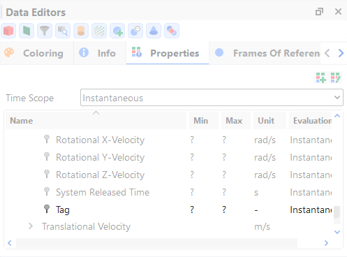
Tag: The tag defined in the Custom Fiber Definition File. This property will only appear if the Show tags on particles module property is enabled and if the Meshed Particles Upscaling is disabled.
Note: Properties generated by this module will only appear if the Upscaling is disabled.Refer to Rocky User Manual (5.1.7. About Meshed Particles Upscaling) for more details.
Create and import into Rocky a Custom Fiber definition file that meets the requirements specified in the Functionality details section.
Ensure that the module is enabled. (From the Data panel, select Modules and then from the Data Editors panel, ensure the Heterogeneous Custom Fiber (Beta) checkbox is enabled.)
From the Data panel, under Modules, select Heterogeneous Custom Fiber (Beta).
From the Data Editors panel, within the Element Pair Properties list, click on the Add button to add all the possible pairs of tags combinations, setting up all the parameters needed.
Set up your simulation as you normally would.
Process and post-process your simulation as you normally would.