


Important: Note that beta features have not been fully tested and validated. Ansys, Inc. makes no commitment to resolve defects reported against these prototype features. However, your feedback will help us improve the overall quality of the product. We will not guarantee that the projects using this beta feature will run successfully when the feature is finally released so you may, therefore, need to modify the projects.
The CFD-Coupled Particle Combustion module enables you to consider
the reaction of coal particles during combustion, with two parallel reactions,  and
and  .
.
In this problem, conduction and convection are considered in the heat transfer modeling, as the local temperature affects the combustion rates. Radiation effects can be included through the Thermal Radiation module. Because of these abilities, it is designed to work with Rocky's 2-Way Fluent coupling method, and Thermal Model.
Note: For more information about the CFD Coupling mode and the Thermal Model options included in Rocky, refer to the Rocky User Manual.
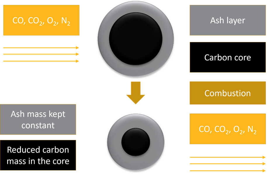
As illustrated in Figure 5.1: Particle combustion over time using the CFD-Coupled Particle Combustion module., the fluid reacts with the solid particle. The carbon core will be combusted, and its mass reduced, whereas the ash layer will not react.
Two reactions occur in parallel. In the first one, the oxygen from the air oxidizes the particle's carbon content. This leads to the oxygen and carbon consumption, carbon dioxide generation and the consequent particle size reduction. Similarly, in the second one, the carbon dioxide from the air reacts with the particle's carbon content to release carbon monoxide, reducing the particle size as well.
The CFD-Coupled Particle Combustion module works by computing the particle reactions rates based on local CFD cell-based information, such as temperature, species concentration, pressure, and flow velocity.
As the reactions occur, the burn-off (quantity of reactive, i.e. carbon, mass consumed) is updated, depending on how the particle mass decreases, also reflecting in its volume. This is done, preserving the particle density constant. On the fluid side, the mass consumption/production of species is sent to Fluent in the form of mass sink/source terms.
The heat of reaction for both reactions are considered to affect only the particle energy equation, and therefore, no corresponding energy source terms are sent to Fluent.
Due to the species transfer between Rocky and Fluent, this module will not work with 1-Way LBM, 1-Way Constant, 1-Way Fluent, nor the 2-Way Fluent Semi-Resolved CFD Coupling modes. The dependencies of the module include the following:
2-Way Fluent CFD Coupling Mode must be enabled in Rocky.
The Thermal Model must be enabled in Rocky.
The module only works for oxygen, nitrogen, carbon dioxide and carbon monoxide, so the fluid species must be named "o2", "n2", "co2" and "co", respectively.
This module also does not support CGM.
Important: Nitrogen needs to be set as last species in Fluent.
The CFD-Coupled Particle Combustion module has some input parameters, split into the Species, Reactions and Advanced tab in the GUI, as illustrated in Figure 5.2: CFD-Coupled Particle Combustion module options under the Species tab. to Figure 5.4: CFD-Coupled Particle Combustion module options under the Advanced Tab.. These parameters are explained below:
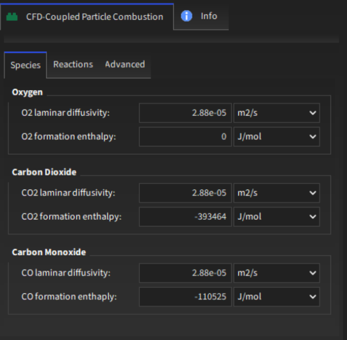
Oxygen:
O2 laminar diffusivity: Oxygen laminar diffusivity.
Range: [Positive values]
O2 formation enthalpy: Oxygen formation enthalpy.
Range: [Negative values]
Carbon Dioxide:
CO2 laminar diffusivity: Carbon dioxide laminar diffusivity.
Range: [Positive values]
CO2 formation enthalpy: Carbon dioxide formation enthalpy.
Range: [Negative values]
Carbon Monoxide:
CO laminar diffusivity: Carbon monoxide laminar diffusivity.
Range: [Positive values]
CO formation enthalpy: Carbon monoxide formation enthalpy.
Range: [Negative values]
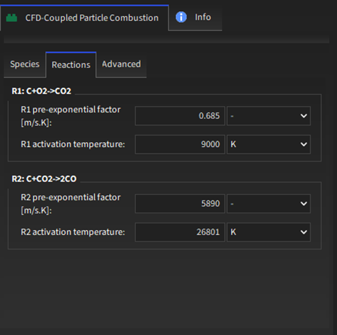
R1: 
R1 pre-exponential factor [m/s.K] : Pre-exponential factor for the carbon-oxygen reaction (R1).
Range: [Positive values]
R1 activation temperature [K]: Activation temperature for the carbon-oxygen reaction (R1).
Range: [Positive values]
R2: 
R2 pre-exponential factor [m/s.K] : Pre-exponential factor for the carbon-carbon dioxide reaction (R2).
Range: [Positive values]
R2 activation temperature [K]: Activation temperature for the carbon-carbon dioxide reaction (R2).
Range: [Positive values]
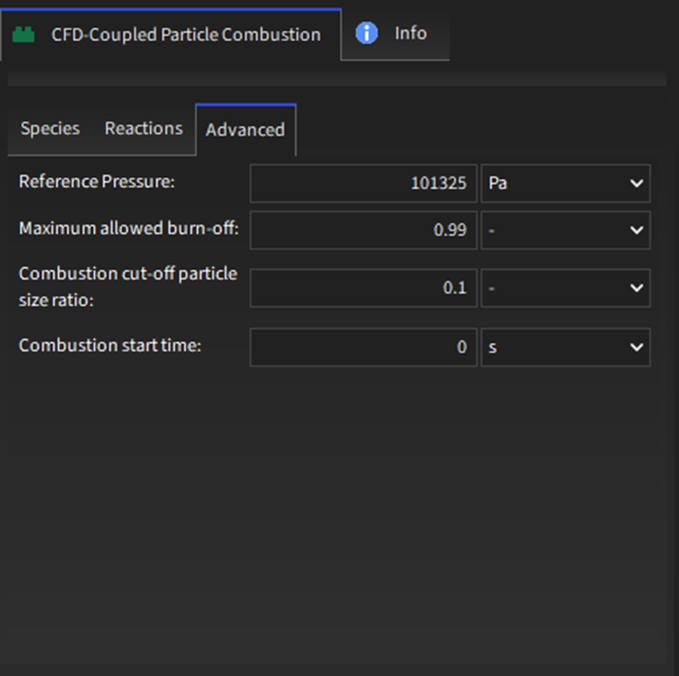
Advanced:
Reference pressure [Pa]: Fluid reference pressure set in Fluent.
Range: [Positive values]
Important: Rocky Solver SDK cannot get the reference pressure from Fluent, so this is mistake-prone.
Maximum allowed burn-off: Maximum burn-off values. Above this value, the particle is removed.
Range: [Positive values]
Combustion cut-off particle size ratio: Minimum ratio between the carbon core size and the particle total size. Below this value, the particle is no longer reactive, but is not removed from the simulation.
Range: [0,1]
Combustion Start Time [s]: Defines the time that combustion starts to take place.
Range: [Positive values]
In addition to the module itself, there will be additional CFD-Coupled Particle Combustion parameters available for Inputs. See the below sections for details.
For Particle Inlets and Volumetric Inlets, a new Modules sub-tab will appear to help you define the initial carbon content of the particles, as shown in Figure 5.5: Options for a Continuous Injection input and Figure 5.6: Options for a Volumetric Inlet input.. Within the table on the Modules sub-tab, the parameters (columns) can be set per Particle set (row), as defined below.
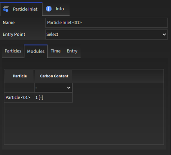
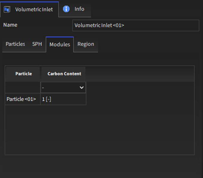
Particle: For each row, lists the Particle set that is defined on the Particles sub-tab.
Range: [Automatically provided]
Carbon content: The mass fraction of carbon that a particle initially has.
Range: [0,1]
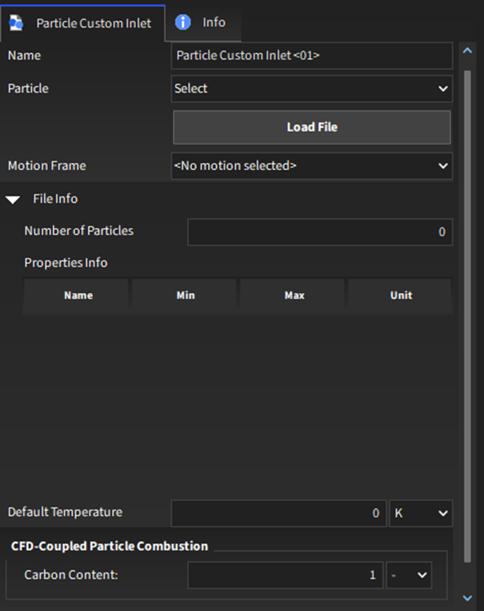
For Custom Inputs, a new CFD-Coupled Particle Combustion sub-tab will appear to help you define the carbon content of the particles, as shown in Figure 5.7: Options for a Custom Inlet input..
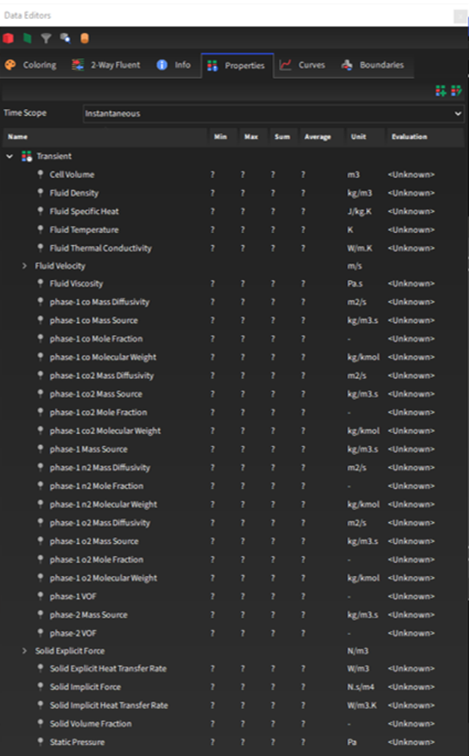
After processing the simulation, some new properties will be available for the main Particles entity (Figure 5.8: Particles properties when the CFD-Coupled Particle Combustion is enabled.). You can choose to analyze these properties in a plot or histogram window. Or you can choose to display this property graphically in a 3D View window.
Note: Refer also to the Graphing (Plot or Histogram) a Data Set Within Rocky topic in the Rocky User Manual.
Note: Refer also to the View Geometries, Particles, Points, and Fluids in 3D topic in the Rocky User Manual.
Carbon content: The mass fraction of carbon that a particle initially has.
Burn-off: The instantaneous burn-off, i.e., the percentage of reactive mass (carbon) already consumed.
Carbon Content: the particle mass percentage of carbon.
Mass Increment: The particle mass increment.
Volume Increment: The particle volume increment.
R1 Ash Layer Resistance: the ash layer resistance for the carbon-oxygen reaction.
R1 Heat of Reaction: the heat due to the carbon-oxygen reaction.
R1 Mass Diffusion Resistance: the mass diffusion resistance for the carbon-oxygen reaction.
R1 Reaction Rate: the rate in which the carbon-oxygen reaction occurs.
R1 Surface Reaction Resistance: the surface reaction resistance for the carbon-oxygen reaction.
R2 Ash Layer Resistance: the ash layer resistance for the carbon-carbon dioxide reaction.
R2 Heat of Reaction: the heat due to the carbon-carbon dioxide reaction.
R2 Mass Diffusion Resistance: the mass diffusion resistance for the carbon-carbon dioxide reaction.
R2 Reaction Rate: the rate in which the carbon-carbon dioxide reaction occurs.
R2 Surface Reaction Resistance: the surface reaction resistance for the carbon-carbon dioxide reaction.
Unreacted Core Size Ratio: the ratio between the carbon core and the particle size.
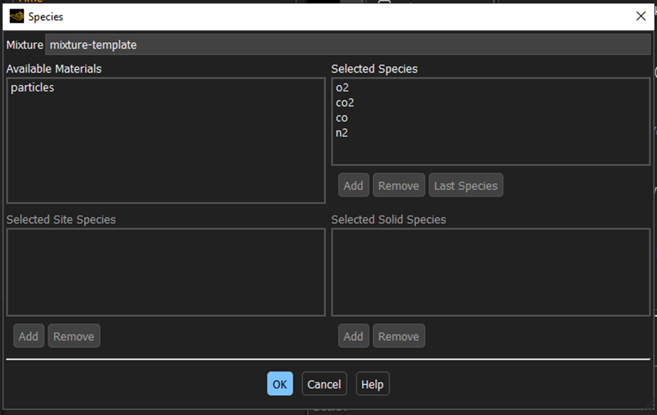
Step 1: Ensure that your case files are set up correctly. Specifically, ensure the Fluent case has the Energy equation and Species Transport activated. Ensure that the species are "o2", "co2", "co", and "n2", which needs to be set as the last species when setting the Mixture in Fluent, as shown below.
Step 2: Ensure that the module is enabled (From the Data panel, select Modules and then from the Data Editors panel, ensure the CFD-Coupled Particle Combustion checkbox is enabled).
Step 3: From the Data panel, under Modules, select the new entry for CFD-Coupled Particle Combustion.
Step 4: From the Data Editors panel, on the CFD-Coupled Particle Combustion tab, enter the values you want.
Step 5: Continue setting up the simulation as you normally would, with the following exceptions:
When setting up your Physics parameters, ensure that the Thermal Model is enabled.
Note: Refer to the Rocky Enable Thermal Modeling Calculations topic in the Rocky User Manual for details.
When setting up your Physics parameters, ensure that the Thermal Model is enabled.
Note: Refer to the Rocky User Manual for setup details and/or refer to the Set or Modify Fluid and/or Air Flow Properties topic in the Rocky User Manual for details.
Step 6: Process the simulation as you normally would.
Note: Refer to the Processing a Simulation topic in the Rocky User Manual.
Step 7: When you are ready to post-process your simulation results, you can make use of the new parameters on the Properties tab for the main Particles entity.
The CFD-Coupled Particle Combustion module considers that a particle,
p, made of reactive (carbon) and non-reactive (ash) material at a
temperature,  , is subjected to a fluid flow (oxygen, nitrogen, carbon dioxide, and carbon
monoxide) at a certain velocity, pressure, and temperature. The combustible particle is
considered using the unreacted core model. The reactive material resides in the core, whereas
the ashes are in the surface, as illustrated by Figure 5.1: Particle combustion over time using the CFD-Coupled Particle Combustion
module..
, is subjected to a fluid flow (oxygen, nitrogen, carbon dioxide, and carbon
monoxide) at a certain velocity, pressure, and temperature. The combustible particle is
considered using the unreacted core model. The reactive material resides in the core, whereas
the ashes are in the surface, as illustrated by Figure 5.1: Particle combustion over time using the CFD-Coupled Particle Combustion
module..
The carbon from the particle reacts with the oxygen, producing carbon dioxide. In parallel to it, the carbon from the particle reacts with carbon dioxide, producing carbon monoxide. The two reactions can be represented by the following equations:


Each rate of change of molar concentration is given by:


where  and
and  are the reaction rates (mol/s) for
  and
and  , respectively.
As in Zhang et al. (2013), the reaction rates are generically given as:

in which  , the effective resistance, is defined as in Wang and Shen (2021):

where:
 is the stoichiometric coefficient. As it is one for both reactions, it
is suppressed for simplicity;
is the stoichiometric coefficient. As it is one for both reactions, it
is suppressed for simplicity; is the reactant species molecular weight (kg/mol);
 is the particle surface area (m3);
 is the reactant species density (kg/m3);
 is the film resistance (m/s);
 is the surface reaction resistance (m/s);
 is the ash layer resistance (m/s).
The film resistance is given as in Zhang et al. (2013) by:

where:
 is the species laminar diffusivity;
Sh is the Sherwood number;
 is the species laminar diffusivity;
The surface reaction resistance is given as in Zhang et al. (2013) by:

where:
 is the pre-exponential factor for
  ;
; is the activation temperature for
  ;
;
The ash layer resistance is given as in Wang and Shen (2021) by:

where:
 is the unreacted core diameter ratio;
 is the effective ash diffusivity;
Assuming that the particle has a constant density, the unreacted core diameter ratio is:

where:
 is the carbon core diameter;
 is the carbon content;
 is the initial carbon content.
And the effective diffusivity is given by:

 and
and  imply the consumption and the generation of species, which reflects on how
the particle mass changes over time:
imply the consumption and the generation of species, which reflects on how
the particle mass changes over time:

where  is the molecular weight of carbon.
Conversely, this also happens for each fluid species, and the mass source terms are sent to Fluent.
For the energy conservation, the first law of thermodynamics is given by:

where:
 is the particle mass;
 is the specific heat;
The heat of reaction rate for  ,
,  , can be obtained by:

where  is the carbon dioxide formation enthalpy.
The heat of reaction rate for  ,
,  , can be obtained by:

where  is the carbon monoxide formation enthalpy.