


Ansys Motion Coupling enables users to prescribe specific, complex motions for their equipment in Ansys Motion and then have those same motions be used in a DEM simulation that is carried out by Rocky.
[HOW-TO VIDEO] Ansys Rocky: Enhance Multibody Dynamics Simulations with Ansys Motion™ Software: https://www.youtube.com/watch?v=tXC9XpfCY1w&list=PL0lZXwHtV6Omiv62KRuPbnZ4oBK8BmDit&index=17
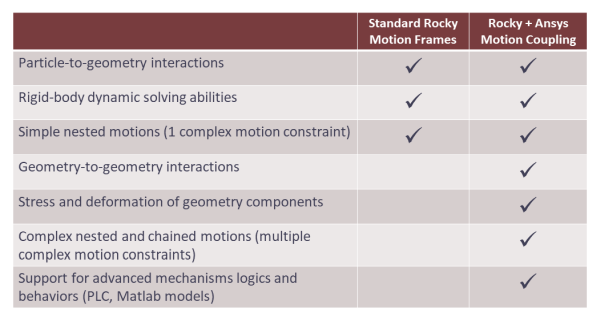
As illustrated in Figure 2.1: Standard Rocky Motion Frames vs. Ansys Motion Coupling Cabilities., when compared to the standard method of defining Motion Frames in Rocky, movements defined with Ansys Motion Coupling have the added benefit of simulating geometry-to-geometry interactions, stress and deformation of geometry components, chained motions, and more.
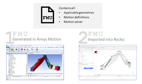
The current implementation of Ansys Motion Coupling includes the installation of one module for the Ansys Motion product, which enables Ansys Motion users to export all applicable geometries, motion definitions, and motion solver files needed for coupling to a Functional Mock-Up Unit (FMU) file.
For Rocky, an internal module named Multibody Dynamics FMU Coupling is used to import that same FMU file and have Rocky use it to simulate both the geometries and geometry motions during the DEM simulation (Figure 2.2: Ansys Motion Coupling FMU file lifecycle.).
This guide assumes that all the following system and program requirements have already been met.
Users of Ansys Motion must ensure all the following:
You have installed one of the compatible versions of Ansys Motion 2025 R2
You have installed the Ansys Motion Module: FMU Setup for Rocky component.
Important: This module is automatically installed when Ansys Rocky software is installed together with or after Ansys Motion software. If you are installing Ansys Motion application after installing Ansys Rocky software on your computer, access the Ansys Customer Portal and download the Ansys Rocky SDK and Modules package to get the module.
Users of Rocky must ensure all the following:
You have installed Rocky version 2025 R2 or later.
You have a valid license for your version of Ansys Motion. It is also required that you have Ansys Motion installed on the same machine as Rocky.
This version of Ansys Motion Coupling has the following limitations:
Gravity direction must match in both Ansys Motion and Rocky.
The Simulation Duration in Ansys Motion must be greater than or equal to the one set in Rocky.
In addition, there are specific limitations for each product, as described below.
This version of Ansys Motion Coupling is currently not compatible with the following Ansys Motion features and functionality:
Rigid bodies with beam elements
Flexible bodies for which you want to have particle interactions
Flexible bodies are supported on the Ansys Motion side of the coupled simulation; however, Rocky will be unable to calculate particle interactions on those flexible bodies.
Including flexible bodies in your coupled simulation might also increase the processing time.
This version of Ansys Motion Coupling is currently not compatible with the following Rocky features and functionality:
Motion Frames: A Rocky project with Ansys Motion Coupling cannot also have Motion Frames. Your simulation will not start processing until all Motion Frames are removed.
Resume processing a stopped simulation: Once you click Stop on the Solver tab, you might be unable to resume processing from the point you stopped.
Extend the duration of a simulation: Once you click Stop on the Solver tab, you might be unable to extend your processing time. Or if you are able to extend your processing time, you might have errors resuming processing.
Save a copy of the partially processed simulation for restart purposes: If you choose to Save as a New Project for Restart your Ansys Motion Coupling project, you might get errors when creating the file. Or, if you are able to create the file, you might be unable to restart it.
Once the System Requirements have been met for the product(s) you are using, you can begin setting up either or both of your projects to perform its part of the Ansys Motion Coupling procedure.
The steps you take in Ansys Motion to enable motions to be coupled with Rocky are as follows:
Open a compatible version of Ansys Motion Preprocessor.
Open an existing subsystem file or create a new subsystem file, setting up your equipment and motions as you normally would.
Tips:
Ensure your Gravity direction in Ansys Motion is set to what you later want to use in Rocky. These must match for the coupling process to work.
Ensure your simulation time (T) in Ansys Motion is greater than Simulation Duration the you later want to use in Rocky.
Because you cannot resume or extend a stopped simulation in Rocky, it is recommended that you make the simulation time longer than you think you need.
It’s recommended to use the default Ansys Motion unit system (m, kg, N, s, V, A), using Ansys Motion Pre or Ansys Motion inside Ansys Mechanical environment. If the user needs to work with millimeters, change the Postprocessor units settings (inside Analysis Settings) to "Convert to Motion-specific (mm kg N s rad)". Manually changing the import scale, when importing geometries to Rocky, will not fix the movements unit scale on Ansys Motion.
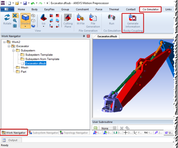
From the Work Navigator panel, under Generate Information, select the .dfsub file representing the geometries and motions you want to couple with Rocky (Figure 2.3: Co-Simulator tab in Ansys Motion.).
From the Co-Simulator tab, click the Generate Information button on the Rocky Coupling toolbar (Figure 2.3: Co-Simulator tab in Ansys Motion.).
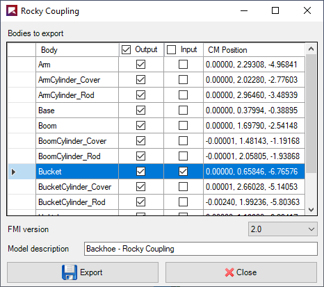
From the Rocky Coupling dialog (Figure 2.4: Rocky Coupling dialog in Ansys Motion.), do the following:
For each of the rigid Body components without beam elements listed, do one or both of the following:
Enable the Output checkbox for each component you want motions to be shared with Rocky.
Enable the Input checkbox for each component you want forces and moments to be collected due to interactions with particles. This data will then be used by the Ansys Motion solver during processing.
Leave the FMI version as it is set by default.
Enter a Model description for the file.
Click the Export button.
From the Save As dialog, verify the file name and location, and then click Save. The progress bar on the Rocky Coupling dialog indicates export status.
Important: To avoid errors during geometry import later, an FMU file should not be manually renamed after it is generated.
From the confirmation message that appears, click OK.
Click Close to close the Rocky Coupling dialog.
At this point, you can share the FMU file with a Rocky user for them to complete the second part of the coupling procedure, or continue with the next step yourself.
Sometimes, if inside the Ansys Motion set-up there are two or more geometries with the same name, or maybe a geometry, a function expression, and a joint load properties named equally, Motion automatically changes the name of the geometry with a prefix ID inside its post-processing. The user can still export the FMU file with this configuration, but he will need to manually fix the geometry name in Rocky’s side (remove the ID).
The steps you take in Rocky to enable motions from Ansys Motion to be coupled with your DEM simulation are as follows:
Open Rocky version or later.
Begin a new simulation project. (From the File menu, click New Project.)
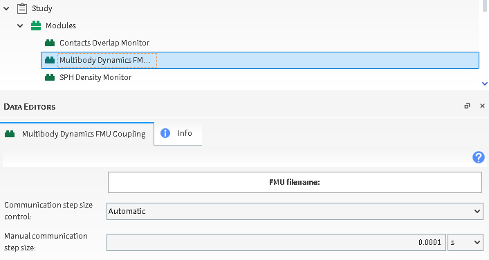
From the Data panel, under Modules, select Multibody Dynamics FMU Coupling.
From the Data Editors panel, on the Multibody Dynamics FMU Coupling tab, do the following (Figure 2.5: Rocky Coupling dialog in Multybody Dynamics FMU Coupling Module.):
Click the FMU filename: button, and then from the Select file to import dialog, locate and select the FMU file you want to use, and then click Open. Save the project now if you are asked to do so.
From the Communication step size control list, select one of the following options:
Automatic: For each time step in the motion tool, Rocky computes 100 timesteps.
Manual: The motion tool’s time step is defined by the Communication step size value.
Rocky timestep: The time step in the motion tool is the same as in Rocky.
If Manual was selected for Communication step size control, then in the Manual communication step size field, enter what time step you want the motion tool to use.
From the Data panel, right-click Geometries, and then click Import Geometry.
From the Select file to import dialog, locate and select one or more files in STL format containing the geometries used in the motion tool project.
Important: It is critical that you import the exact same geometry parts required for the coupling and with the same exact names. Otherwise, the motions may not work. If you later need to re-import a newer version of this FMU file, ensure that you also update the geometry files. See Reimport an updated FMU file into Rocky procedure for more details.
From the Import File Info dialog, select the options you want, and then click OK. The Geometries list is populated with the components that were exported out of the motion tool.
Set up the rest of your simulation as you normally would, being careful to ensure the following:
You have defined the gravity direction in Rocky to match what was set in the motion tool.
You have defined the Simulation Duration in Rocky to be less than or equal to the duration that was set in the motion tool.
Process your simulation and analyze the results in Rocky as you normally would.
Once you have started processing the simulation, avoid stopping the simulation as you will be unable to resume processing once it has started. Refer to the Limitations section for more details.
If you have already created a FMU file in Ansys Motion but then later removed, added, or renamed bodies in the Subsystem file, you can just follow the same steps you did originally to export the file again.
Use the below procedure if you have already imported a prior version of the FMU file into Rocky, but now have a newer version of the FMU file with which to replace it.
With the Rocky project open that contains information from the FMU file you want to update, do the following:
Remove and then re-import the geometries added by the FMU file by doing the following:
From the Data panel, under Geometries, select or multi-select all the components that were originally imported by the FMU file.
Right-click the selected geometries, and then click Remove Geometries.
Re-import the geometries via the updated FMU file as you normally would.
Alternatively, if you made only small changes to the bodies in Ansys Motion, you can make those changes to individual Geometries in Rocky without removing all of them and importing them again. However, you must ensure that the changes you make exactly match the information in the FMU file you import into the Ansys Motion Coupling module.
Re-import the FMU file into the Ansys Motion Coupling module by following the Rocky setup for coupling with Ansys Motion procedure.
Set up, process, and analyze the results of your simulation as you normally would.
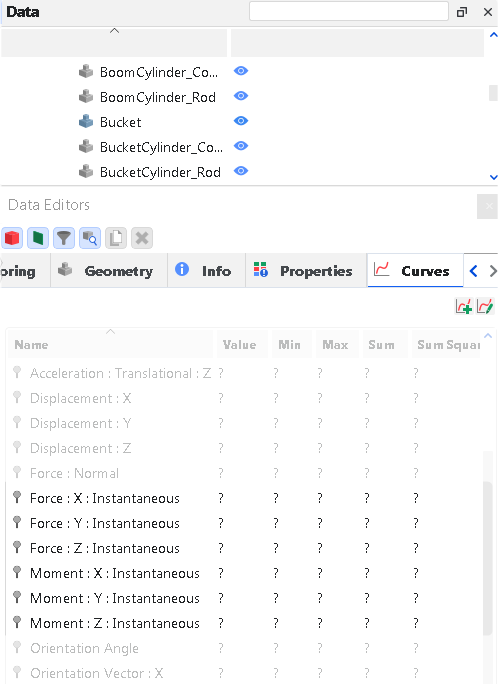
After processing your coupled simulation, you will have new Curves for your geometry components, depending upon whether they were selected to be exported out of Ansys Motion as an Output body (Figure 2.6: Standard Ansys Motion Coupling Curves for a geometry that was exported out of Ansys Motion as an Output.) – which has no interactions with Particles – or an Input body (Figure 2.7: Additional Ansys Motion Coupling Curves for a geometry that was exported out of Ansys Motion as an Input.) – which does have interactions with Particles.
Figure 2.6: Standard Ansys Motion Coupling Curves for a geometry that was exported out of Ansys Motion as an Output.
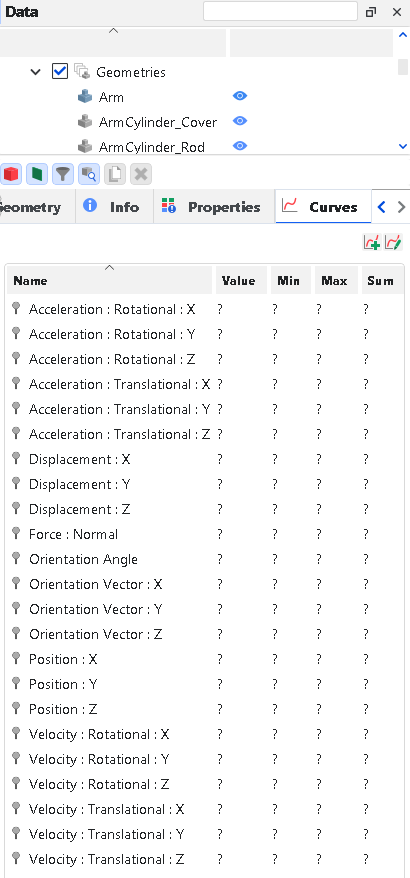
Figure 2.7: Additional Ansys Motion Coupling Curves for a geometry that was exported out of Ansys Motion as an Input.
These Curves are explained below:
Acceleration : Rotational : X: The amount of rotational (angular) acceleration for the geometry in the X direction as measured from the Center of Mass.
Acceleration : Rotational : Y: The amount of rotational (angular) acceleration for the geometry in the Y direction as measured from the Center of Mass.
Acceleration : Rotational : Z: The amount of rotational (angular) acceleration for the geometry in the Z direction as measured from the Center of Mass.
Acceleration : Translational : X: The amount of translational acceleration for the geometry in the X direction as measured from the Center of Mass.
Acceleration : Translational : Y: The amount of translational acceleration for the geometry in the Y direction as measured from the Center of Mass.
Acceleration : Translational : Z: The amount of translational acceleration for the geometry in the Z direction as measured from the Center of Mass.
Displacement : X: The distance the geometry was displaced in the X direction.
Displacement : Y: The distance the geometry was displaced in the Y direction.
Displacement : Z: The distance the geometry was displaced in the Z direction.
Force : X : Instantaneous: Only for geometries that were exported out of Ansys Motion as an Input body, this provides the force applied to the geometry along the X axis.
Force : Y : Instantaneous: Only for geometries that were exported out of Ansys Motion as an Input body, this provides the force applied to the geometry along the Y axis.
Force : Z : Instantaneous: Only for geometries that were exported out of Ansys Motion as an Input body, this provides the force applied to the geometry along the Z axis.
Moment : X: Instantaneous: Only for geometries that were exported out of Ansys Motion as an Input body, this provides the moment (torque) applied to the geometry’s Center of Mass around the X axis.
Moment : Y: Instantaneous : Only for geometries that were exported out of Ansys Motion as an Input body, this provides the moment (torque) applied to the geometry’s Center of Mass along the Y axis.
Moment : Z: Instantaneous: Only for geometries that were exported out of Ansys Motion as an Input body, this provides the moment (torque) applied to the geometry’s Center of Mass along the Z axis.
Orientation Angle: The angle the geometry is rotated around the Orientation Vector.
Orientation Vector X: The X component defining the vector around which the geometry is rotated.
Orientation Vector Y: The Y component defining the vector around which the geometry is rotated.
Orientation Vector Z: The Z component defining the vector around which the geometry is rotated.
Position X: The global coordinate of the geometry’s Center of Mass as specified in the X direction.
Position Y: The global coordinate of the geometry’s Center of Mass as specified in the Y direction.
Position Z: The global coordinate of the geometry’s Center of Mass as specified in the Z direction.
Velocity : Rotational : X: The amount of rotational (angular) velocity for the geometry in the X direction as measured from the Center of Mass.
Velocity : Rotational : Y: The amount of rotational (angular) velocity for the geometry in the Y direction as measured from the Center of Mass.
Velocity : Rotational : Z: The amount of rotational (angular) velocity for the geometry in the Z direction as measured from the Center of Mass.
Velocity : Translational : X: The amount of translational velocity for the geometry in the X direction as measured from the Center of Mass.
Velocity : Translational : Y: The amount of translational velocity for the geometry in the Y direction as measured from the Center of Mass.
Velocity : Translational : Z: The amount of translational velocity for the geometry in the Z direction as measured from the Center of Mass.
If you have trouble with either creating the FMU file in Ansys Motion or importing the FMU file in Rocky, see the sections below for solutions.
If you have trouble finding the modules in either program, refer instead to the Ansys Motion Coupling Installation Guide.
The Generate Information | Rocky Coupling button will only appear on the Co-Simulator tab if you have successfully installed the Ansys Motion Coupling component.
If after clicking the Generate Information button on the Rocky Coupling toolbar, you get a message similar to the one shown in Figure 2.8: "Flexible Bodies" message in Ansys Motion., then flexible bodies have been detected in your Ansys Motion project.

If you require these flexible bodies for proper motion setup, you can click OK and continue with your FMU file generation as usual. Just be aware that the flexible bodies will not be able to interact with particles in Rocky when the coupled simulation is processed. Also know that a coupled simulation with flexible bodies might take longer to process.
If you do not require these flexible bodies for proper motion setup, you can help reduce processing time later by removing the flexible bodies from the Ansys Motion project, and then generating the FMU file again. (Click OK on this message, cancel out of the FMU generation dialog, remove those flexible bodies from your Ansys Motion project, and then click the Generate Information | Rocky Coupling button again.) If you have properly removed the flexible bodies, then you should no longer see the message shown in Figure 2.7: Additional Ansys Motion Coupling Curves for a geometry that was exported out of Ansys Motion as an Input..
You must have a valid Ansys Motion license for one of the compatible versions in order for the motion solver bundled with the imported FMU file to work inside Rocky and also have Ansys Motion installed in the same machine as Rocky.. Refer to the System Requirements section for details about compatible versions.
If you do not have this kind of license for Ansys, please contact your Ansys and/or Rocky representative for assistance.
Whenever you have updated your FMU file in Ansys Motion, it is necessary to ensure that the geometries in Rocky match the bodies within the FMU file. The easiest way to ensure this is to remove all geometry components previously imported by the old FMU file, and then re-import the geometries via the new FMU file.
If you have duplicated geometries in your Rocky project, then you might have re-imported geometries from the FMU file before removing the old geometry components. Refer to the Re-import an updated FMU file into Rocky section for specific steps.
If after you start processing your coupled simulation in Rocky, you get an error similar to the one shown in Figure 2.9: Ansys License Manager Error in Rocky., then you might not have an active license for your Ansys Motion version. Refer to the System Requirements section for details about compatible versions.
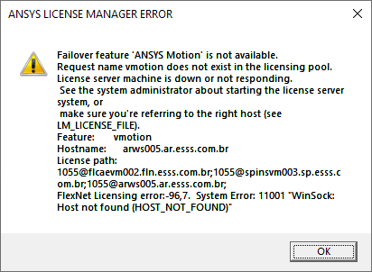
While you do not need to have a copy of Ansys Motion on the same machine you are running Rocky, you do need to have an active license of Ansys in order to process the coupled simulation in Rocky. Ensure your system meets the System Requirements, and then try processing your coupled simulation again.