


The direct-embedding workflow uses standard structural, thermal, and coupled-field elements to model the embedded members and base elements.
The following topics are available for direct embedding:
Mechanical APDL supports line and shell elements as embedded members.
The embedded line elements and the base elements are bonded at the cross-sections of embedded elements nodes. Although the connections between the cross-sections of the embedded members and the base material are assumed to be bonded, some connection flexibilities including warping and section area changes are allowed.
The embedded shell elements and the base elements are bonded at connection points. The location of connection points are shown in "3-D Special-Purpose Smeared Reinforcing Element Description for Shell Embedding ". At these connection points, compatibility of deformation between the shell and solid elements is enforced.
The connection constraints are modeled with special-purpose REINF265 reinforcing elements (created automatically). For structural problems, the special-purpose REINF265 elements contribute no additional structural stiffness, mass, or external forces. For thermal problems, they contribute no additional thermal conduction, damping, or external heat. For piezoelectric problems, they contribute no additional elastic stiffness, piezoelectric coupling coefficients, dielectric permittivity, or electrical charge.
The stiffness or external load on the overlapped regions occupied by both the embedded and base elements can be over-estimated due to the base material not being subtracted. For solution accuracy, the stiffness of the embedded elements is assumed to be larger than that of the base elements. Similarly, in a thermal analysis, embedded elements are assumed to have higher thermal conductivity than that of the base elements. In an electrical analysis, embedded elements are assumed to have lower electrical resistivities than that of the base elements.
Following are the element types supported for embedding and their base element types. "Y" indicates a valid combination of embedded and base elements, and "-" indicates an invalid combination. Only the common degrees of freedom of embedded and base elements are connected.
Table 14.3: Supported Elements for Direct Embedding
| Embedded Element Type | Base Element Type | ||||
| SOLID185, SOLID186, SOLID187, SOLID285 | SOLID278, SOLID279, SOLID291 | SOLID225, SOLID226, SOLID227 | |||
| KEYOPT(1) = 11 | KEYOPT(1) = 110 | KEYOPT(1) = 111 | |||
| LINK180 | Y | - | Y | - | Y |
| BEAM188, BEAM189 | Y | - | Y | - | Y |
| LINK33 | - | Y | Y | Y | Y |
| LINK228 KEYOPT(1) = 11 | Y | Y | Y | Y | Y |
| LINK228 KEYOPT(1) = 110 | - | Y | Y | Y | Y |
| LINK228 KEYOPT(1) = 111 | Y | Y | Y | Y | Y |
| LINK228 KEYOPT(1) = 101 | Y | - | Y | Y | Y |
| LINK228 KEYOPT(1) = 1001 | Y | - | Y | - | - |
All features of the supported base element types are available with these exceptions:
Following is the direct element-embedding process:
Create the base elements and the elements to be embedded.
Select the base elements and the elements to be embedded.
Optional step: If required, optimize the base elements according to the elements to be embedded. For more details about the requirements and limitations, refer to the MSHOPTIM command.
Embed the elements (EEMBED).
Inspect and verify the connections.
As shown in the following input example, you can adjust the translucency of the base elements to show the special-purpose REINF265 elements representing the bonded connection between the base and embedded elements:
Example 14.11: Defining Element Embedding
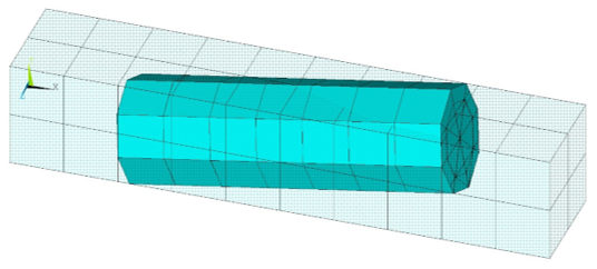
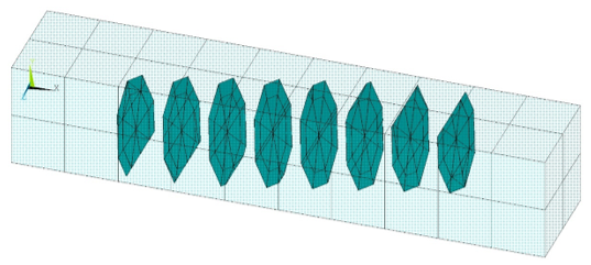
/batch,list
/title, Example input data for element embedding
/prep7
!
! Define material properties
!
mp,nuxy,1,0.3   ! base material
mp,ex,1,1e6
mp,nuxy,2,0.3   ! embedded material
mp,ex,2,1e9
!
! Define base elements
!
et,1,185
mat,1
block,0,10,-1,1,-1,1
esize,1
vmesh,1
!
! Define beam elements to be embedded
!
et,2,188
sect,2,beam,csolid
secd,1
k,101,2,-0.5,
k,102,8,0.5
l,101,102
lesize,all,1,
secn,2
mat,2
type,2
lmesh,13
!
! Inspect BEAM and base SOLID elements
!
esel,s,type,,1
/trlcy,elem,0.9
esel,all
/eshap,1
/view,1,1,2,3
! Activate the expanded element shapes
/eshape,1
/show,png,rev,,8,'beam_and_solid_elements'
eplot
/show,close
!
! Create element embedding
!
eembed
!
! Inspect newly created reinforcing elements
!
esel,u,ename,,188
/show,png,rev,,8,'reinf_and_base_elements'
eplot
/show,close
The input listing in Example 14.11: Defining Element Embedding generates the following output:
The element types supported for embedding and their base element types are shown in the table below:
SHELL181 and SHELL281 elements associated with the GENS section type are not supported.
The following is the direct element-embedding process:
Create the base elements and the elements to be embedded.
Select the base elements and the elements to be embedded.
Optional step: If required, optimize the base elements according to the elements to be embedded. For more details about the requirements and limitations, refer to the MSHOPTIM command.
Embed the elements (EEMBED).
Inspect and verify the connections.
As shown in the following input example, you can adjust the translucency of the base elements to show the special-purpose REINF265 elements representing the bonded connection between the base and embedded elements:
Example 14.12: Defining Element Embedding
/batch,list
/title, Example input data for shell embedding
/prep7
!
! Define material properties
!
mp,ex,1,1e3
mp,nuxy,1,0.3

mp,ex,2,1e4
mp,nuxy,2,0.3

!
! Define base elements
!
et,1,185
block,0,3,0,1,0,1
esize,1
type,1
mat,1
vmesh,all
!
! Define shell elements
!
k,11,0,1/2,0
k,12,3,1/2,0
k,13,3,1/2,1
k,14,0,1/2,1
a,11,12,13,14

et,2,181
sectype,1,shell
secdata,0.2

type,2
secnum,1
mat,2
amesh,7
!
! Create element embedding
!
EEMBED

/view,1,1,2,3
esel,s,ename,,185
/trlcy,elem,0.8
esel,s,ename,,181
/trlcy,elem,0.4
esel,s,ename,,265
/color,elem,red
/eshap,1
alls
eplot
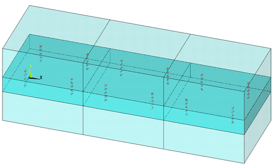
The input listing in Example 14.11: Defining Element Embedding generates the following output:
Figure 14.23: Shell embedded in Solid element (with Translucent Base and Shell Elements, connections are shown in red color)
Accuracy of the results may be affected without proper meshing controls at the location where the base and embedded elements intersect. It is recommended to use comparable effective element sizes for both the embedded and base elements at the intersecting regions. For example, when the embedded and base elements have the same interpolation order, the recommended base-to-shell element size ratio is 1.0. When embedding linear shell elements into quadratic base elements, the recommended ratio is 2.0, and when embedding quadratic shell elements into linear base elements, the recommended ratio is 0.5.
When embedding line or shell elements in tetrahedral shaped base elements, it is recommended to optimize the base elements using the MSHOPTIM command.
Sufficient refinement of both base and embedded elements is necessary to accurately capture the high solution gradients often present at material discontinuities.
Maintaining a consistent element size ratio between the base and embedded elements is needed when performing convergence studies.
The mass, stiffness, and external load on the overlapped regions occupied by both the embedded and base elements can be over-estimated due to the base material not being subtracted.
When base elements use mixed formulations, such as SOLID185 with KEYOPT(6) = 1, degree-of-freedom boundary conditions cannot be directly applied to embedded members.