


The separation process of two crack surfaces includes crack initiation and crack-growth. Generally, crack initiation and growth adopt different criteria to identify the starting points and crack behaviors.
For crack initiation where the singularity is not considered, a local indicator is usually defined to determine where and when a crack is initialized. In this case, the maximum principal stress is the indicator that is calculated and checked at every finite element node at the end of a stress-analysis step. When the criterion is satisfied, one or more cracks are inserted at the critical locations in appropriate shapes and sizes.
The most general approach is the energy-release-rate method. Driving the crack-growth requires an increase in the surface energy to separate the two crack surfaces. When the surface energy reaches the critical value, the crack surfaces separate and the crack grows.
A simple criterion based on the energy-release rate can be expressed as:

where  is the so-called critical fracture energy required to separate the two
crack surfaces. It is considered to be a material property, independent of the applied
loads and the geometry of the body, and is often referred to as the fracture
toughness.
is the so-called critical fracture energy required to separate the two
crack surfaces. It is considered to be a material property, independent of the applied
loads and the geometry of the body, and is often referred to as the fracture
toughness.
The following topics are available to help you understand crack-growth analysis:
Defects and voids can occur during the lifetimes of materials and structures, and micro-damages can grow to become catastrophic. Mechanical APDL provides the material criteria and an adaptive algorithm to identify high-risk locations in models. You can either specify the locations, shapes, and sizes for initialized cracks, or you can allow the adaptive crack-initiation algorithm to calculate this information automatically from the model deformations and geometries.
Crack-growth modeling is essentially based on the fracture parameters and criteria used. Many criteria exist in the literature. Mechanical APDL offers two common fracture criteria for static crack-growth simulation:
Use Separating, Morphing, Adaptive and Remeshing Technology (SMART) to model static crack-growth.
In LEFM, the J-integral is equivalent to the energy-release rate and is therefore also related to the stress-intensity factor. In nonlinear fracture mechanics (NLFM), where the material behavior is described via the general Ramberg-Osgood relation, the J-integral characterizes the stress at the crack tip. It can therefore be used as a crack-growth criterion similar to the stress-intensity factor.
The J-integral value is calculated using the domain integration method (CINT,TYPE,JINT). Critical values must be measured according to standard experiments.
The fracture criterion is expressed as:

Within the context of linear elastic fracture mechanics (LEFM), a crack grows when the crack-tip stress exceeds a certain critical value.
The stress-intensity
factor  determines the amplitude of the crack-tip stress for a given
geometry and loading case. We can therefore assume that a crack will grow when
determines the amplitude of the crack-tip stress for a given
geometry and loading case. We can therefore assume that a crack will grow when
 reaches the critical value. This assumption implies that a
crack-growth criterion can be formulated where the stress-intensity factor for a
given case is compared to this critical value.
reaches the critical value. This assumption implies that a
crack-growth criterion can be formulated where the stress-intensity factor for a
given case is compared to this critical value.
The value of the stress-intensity factor is calculated using the interaction integral method
(CINT,TYPE,SIFS). The critical value must be known from
experimental measurements and is usually denoted as  . It is considered to be material property and is referred to
as the fracture toughness.
. It is considered to be material property and is referred to
as the fracture toughness.
For Mode- crack-growth, the fracture toughness is expressed as:

For a mixed-mode situation, a crack grows when the
equivalent stress-intensity factor ( ) reaches the mode-I fracture toughness (
 ).
).

There are various formulations for equivalent SIF in the literature [1], e.g., maximum tangential stress (MTS) criterion.
When structural components are subject to cyclic loading, a crack can grow well
before the critical characteristics of the materials such as the yield stress and
the critical stress-intensity factor  are reached. A typical fatigue crack-growth law formulates the
crack-extension increment as function of stress-intensity factor and stress
ratio:
are reached. A typical fatigue crack-growth law formulates the
crack-extension increment as function of stress-intensity factor and stress
ratio:

where  is the crack extension,
  is the fatigue cycle count,
  is the crack-growth rate per loading cycle due to fatigue,
 is the stress-intensity factor, and
  is the stress ratio.
This figure is a typical log-log plot showing three distinct regions for the fatigue crack-growth process observed from experimental testing:
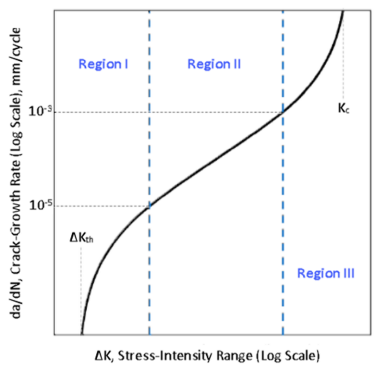
Region I shows the crack starting to grow after the threshold  is reached, but with very limited crack-growth. Region II shows
the crack growing linearly with the stress-intensity factor. Region III shows
general unstable crack-growth.
is reached, but with very limited crack-growth. Region II shows
the crack growing linearly with the stress-intensity factor. Region III shows
general unstable crack-growth.
The crack-growth rate is typically dependent on the stress-intensity-factor range
 , calculated from the maximum and minimum loads during a fatigue
load cycle. The stress ratio for a fatigue cycle is
defined as:
, calculated from the maximum and minimum loads during a fatigue
load cycle. The stress ratio for a fatigue cycle is
defined as:

where  and
and  are the stress-intensity factors at the minimum and maximum loads
in a fatigue cycle, respectively.
are the stress-intensity factors at the minimum and maximum loads
in a fatigue cycle, respectively.  is always less than one.
The stress-intensity-factor range  can be rewritten as:

For mixed-mode fatigue crack-growth, is based on the equivalent stress-intensity factor, commonly using
the maximum tangential stress (MTS) criterion.

where
 is the direction of propagation (kink angle) based on MTS
criterion. is the direction of propagation (kink angle) based on MTS
criterion. |
Note that in addition to MTS, other formulations of equivalent SIF for mixed-mode fracture are also available in literature [1].
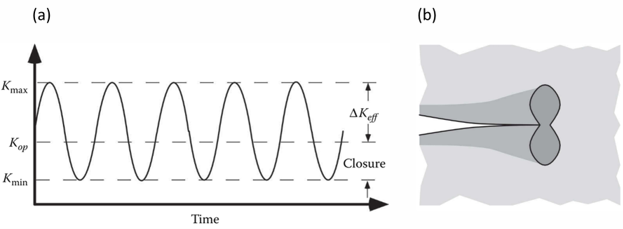
Elber[12] introduced the concept of crack closure (contact
between crack faces at low but still non-zero load). He proposed that during a
fatigue cycle, the crack remains closed below the load level corresponding to
 and, consequently, the effective stress-intensity-factor range
 driving the crack-growth is less than
  . A measure of crack closure is the
  ratio, defined as:

Plasticity-induced closure, a prominent mechanism of fatigue crack closure,
results from the residual stress in the plastic wake behind the crack. Researchers
have attempted to relate crack closure to various load variables such as maximum
load, stress ratio ( ), etc. Some empirical relations, such as the Newman[10] crack-opening stress function, are readily available in
the literature.
), etc. Some empirical relations, such as the Newman[10] crack-opening stress function, are readily available in
the literature.
The following topics about fatigue crack-growth mechanics are available:
A common fatigue crack-growth model is Paris' Law,[2] which relates the stress-intensity-factor range to the crack-growth rate for region II under a fatigue-stress regime:

where,  and
and  are the Paris' Law constants dependent on the material
characteristics and stress ratio, and
are the Paris' Law constants dependent on the material
characteristics and stress ratio, and  is the stress-intensity-factor range during the fatigue cycle.
Paris' Law is restricted to region II of the fatigue crack-growth
process.
is the stress-intensity-factor range during the fatigue cycle.
Paris' Law is restricted to region II of the fatigue crack-growth
process.
These commands define the Paris' Law model data:
The constants can be defined as a function of temperature
(TBTEMP or TBFIELD,TEMP) and/or stress
ratio (TBFIELD,SRAT). As fatigue crack-growth data is
typically handled on a logarithmic scale, Mechanical APDL interpolates
log( ) linearly between temperatures and/or stress ratios. The
constant
) linearly between temperatures and/or stress ratios. The
constant  is first converted to log(
 ) at each field value (TEMP and/or SRAT), then
log(
) at each field value (TEMP and/or SRAT), then
log( ) and
) and  are interpolated linearly between them.
You can specify a crack-closure model (using the same material ID) with Paris’ law. The effective stress-intensity-factor range is then used for the crack-growth rate calculations. A crack-closure model is ignored if the Paris’ Law constants are a function of stress ratio (TBFIELD,SRAT).
Walker's[6] modified form of Paris' Law incorporates the effect of the stress ratio on the fatigue crack-growth rate:

where  ,
,  , and
, and  are the material fatigue crack-growth parameters.
 represents the sensitivity of the crack-growth rate to the
stress ratio and lies between 0 and 1. For
represents the sensitivity of the crack-growth rate to the
stress ratio and lies between 0 and 1. For  , the crack-growth rate is insensitive to
  and the equation reduces to Paris’ Law.
Similar to Paris’ Law, the Walker equation applies to region II only, corresponding to stable fatigue crack-growth.
These commands define the Walker equation and data:
The constants can be defined as a function of temperature
(TBTEMP or TBFIELD,TEMP).
Log(), , and follow linear interpolation between temperatures.
Forman[7] proposed a governing equation for
fatigue crack propagation that can be extended to the unstable crack-growth
region. As the maximum stress-intensity-factor  becomes comparable to the fracture toughness
  , the fatigue crack-growth rate experiences significant
acceleration and the crack-growth undergoes a transition from region II to region III. Forman's
equation, applicable to both region II and region III, is given as:
, the fatigue crack-growth rate experiences significant
acceleration and the crack-growth undergoes a transition from region II to region III. Forman's
equation, applicable to both region II and region III, is given as:

where  ,
,  , and
, and  are the material fatigue crack-growth parameters. As
 nears
nears  ,
,  approaches infinity, suggesting unstable crack-growth.
These commands define the Forman equation and data:
The constants can be defined as a function of temperature
(TBTEMP or TBFIELD,TEMP).
Log(), , and follow linear interpolation between temperatures.
A table option enables you to create your own crack-propagation law based on
data points that you specify. You provide the discrete data points
 and
and  in the following equation to specify a table-based
relation:
in the following equation to specify a table-based
relation:

Mechanical APDL interpolates data linearly on a logarithmic scale between two data points. Beyond the extreme data points, the program applies the constant-extrapolation rule.
You can use this option to define a general fatigue law which can be based on an experimental dataset.
These commands define the tabular fatigue law and data:


The fatigue law datapoints can be defined as a function of temperature
(TBTEMP or TBFIELD,TEMP) and/or stress
ratio (TBFIELD,SRAT). For field-dependent data points, the
program interpolates log() at the neighboring log( ) values corresponding to your TBPT input,
and then finally between those neighboring values. If you specify one field
variable (TEMP or SRAT), follows linear interpolation between the field values. If you
specify both field variables, the program uses linear-multivariate
interpolation.
) values corresponding to your TBPT input,
and then finally between those neighboring values. If you specify one field
variable (TEMP or SRAT), follows linear interpolation between the field values. If you
specify both field variables, the program uses linear-multivariate
interpolation.
You can specify a crack-closure model (using the same material ID) with the tabular fatigue law. The effective stress-intensity-factor range is then used for the crack-growth rate calculations. A crack-closure model is ignored if the fatigue law datapoints are a function of stress ratio (TBFIELD,SRAT).
Developed originally by NASA Johnson Space Center, NASGRO is a software program that performs fracture and fatigue crack-growth calculations. Since version 4, the software has been developed jointly by NASA and Southwest Research Institute.[8] The NASGRO equation is a general form of fatigue law, applicable in all three fatigue crack-growth regions of a typical fatigue crack-growth curve and incorporating R-ratio dependence.
The following topics are available:
The NASGRO fatigue crack-growth calculations are based on the following equation:[9]

where  ,
,  ,
,  , and
, and  are empirical parameters, and
  is Newman’s crack-opening function.[10]
The equation incorporates the effects of stress ratio  , threshold stress-intensity-factor range
  , and fracture toughness
  on the crack-growth rate.
Newman’s crack opening function  is the ratio of crack-opening stress-intensity factor to
the maximum stress-intensity factor. The function is used to model the
effect of plasticity-induced crack closure at the crack front and is given
by:[10]
is the ratio of crack-opening stress-intensity factor to
the maximum stress-intensity factor. The function is used to model the
effect of plasticity-induced crack closure at the crack front and is given
by:[10]

where:

|

|

|

|
 is the maximum far-field stress during a load cycle,
normalized with respect to the flow stress
is the maximum far-field stress during a load cycle,
normalized with respect to the flow stress  . The flow stress is taken to be the average of uniaxial
yield stress and uniaxial ultimate tensile strength.[10] The parameter
. The flow stress is taken to be the average of uniaxial
yield stress and uniaxial ultimate tensile strength.[10] The parameter  is the constraint factor, lying between 1 (plane stress)
and 3 (plane strain). The normalized stress
is the constraint factor, lying between 1 (plane stress)
and 3 (plane strain). The normalized stress  and
and  are inputs that you provide, used for calculating function
 in the NASGRO equation.
The threshold stress-intensity-factor range  for a given material is typically a function of the stress
ratio
for a given material is typically a function of the stress
ratio  . The relationship for a long crack is approximated
by:[9]
. The relationship for a long crack is approximated
by:[9]

where  is the threshold stress-intensity-factor range for
 , and
, and  is an empirical parameter.


The base equation for NASGRO v. 4 is identical to that of v. 3:[11]
The empirical relationship for threshold stress-intensity-factor range
, however, is different and provides a better fit at
negative stress ratios via an additional parameter  . The modified relationship between and is given by:

where  is the threshold stress-intensity-factor range for a high
stress ratio (close to 1), and
is the threshold stress-intensity-factor range for a high
stress ratio (close to 1), and  and
and  are empirical parameters.
Fitted parameters for some metallic materials relevant to aircraft structures can be found in Forman et al. (2005).


You can use any of the following crack-closure functions with either Paris’ law
(TB,CGCR,MaterialID,,,PARIS)
or the tabular fatigue law
(TB,CGCR,MaterialID,,,TFDK)
in a fatigue crack-growth simulation:
Based on experiments on 2024-T3 aluminum alloy sheets, Elber[12] proposed the following empirical relation for
crack-closure parameter :

The function is valid for a stress ratio in the range -0.1 ≤ R ≤ 0.7. Use it only for aluminum alloy 2024-T3 or similar grades at room temperature.
This command defines the Elber closure function:
TB,CGCR,MaterialID,,,ELBER |
Schijve[13] also studied 2024-T3 aluminum
alloy sheets and gave the following relation for closure parameter
as a function of stress ratio:

The function is valid for a stress ratio in the range -1 ≤ R ≤ 0.54. Use it only for aluminum alloy 2024-T3 or similar grades at room temperature.
This command defines the Schijve closure function:
TB,CGCR,MaterialID,,,SCHIJVE |
Based on finite element study of a CCT specimen of an elastic-plastic
material, Newman[10] presented a crack opening
function to estimate crack closure. It evaluates  , a function of stress ratio, stress level and
three-dimensional constraint. The relation is given by:
, a function of stress ratio, stress level and
three-dimensional constraint. The relation is given by:

where:

|

|

|

|
 is the maximum far-field stress during a load cycle,
normalized with respect to the flow stress
is the maximum far-field stress during a load cycle,
normalized with respect to the flow stress  . The flow stress is taken to be the average of uniaxial
yield stress and uniaxial ultimate tensile strength.[10] The parameter
. The flow stress is taken to be the average of uniaxial
yield stress and uniaxial ultimate tensile strength.[10] The parameter  is the constraint factor, lying between 1 (plane stress)
and 3 (plane strain). The normalized stress
is the constraint factor, lying between 1 (plane stress)
and 3 (plane strain). The normalized stress  and
and  are user inputs.
The corresponding is evaluated as:

These commands define the Newman closure function:


A typical fatigue crack-growth calculation requires:
Calculating
 at the maximum load.
Evaluating
 , and
, and  if a crack-closure model is specified.
Defining the incremental number of cycles
 to calculate the crack increment
  ,
, or
Defining the crack increment
 to calculate the incremental number of cycles
 .
.Repeating the same calculation with the new crack extension.
Stopping the analysis when the specified stop-criterion (such as maximum crack extension) is reached.
The calculation of  (and
(and  ) is performed numerically during the analysis at each
substep.
) is performed numerically during the analysis at each
substep.
The determination of or depends on the fatigue crack-growth method used.
Fatigue crack-growth can be modeled using either of these methods:
Life-cycle (LC)– Uses crack-extension increment
to calculate the load-cycle increment .Cycle-by-cycle (CBC) – Uses the load-cycle increment
to calculate crack-extension increment .
Mechanical APDL offers two methods for simulating fatigue crack-growth:
XFEM-based (supports Paris' Law only).
A considerable body of literature concerning fatigue crack-growth simulation exists. The references cited in this document are by no means exhaustive.
Wang, Y., Wang, W., Zhang, B. and Li, C.Q. A review on mixed mode fracture of metals. Engineering Fracture Mechanics. 235: 107126 (2020).
Paris, P. C., M.P. Gomez, and W.P. Anderson. TA Rational Analytic Theory of Fatigue. The Trend in Engineering. 13: 9-14 (1961).
Anderson, T. L. Fracture Mechanics: Fundamentals and Applications. CRC Press, 2005.
Erdogan, F. and G. C. Sih. On the Crack Extension in Plates under Plane Loading and Transverse Shear. ASME Journal of Basic Engineering. 85: 519-527 (1963).
Tada, H., P. C. Paris, and G. R. Irwin. The Stress Analysis of Cracks Handbook. 2nd ed. St. Louis: Paris Productions, 1985.
Walker, K. The Effect of Stress Ratio During Crack Propagation and Fatigue for 2024-T3 and 7075-T6 Aluminum. Effects of Environment and Complex Load History on Fatigue Life. Ed. M. Rosenfeld. ASTM International. 1-14 (1970).
Forman, R. G., V. E. Kearney, and R. M. Engle. Numerical Analysis of Crack Propagation in Cyclic-Loaded Structures. ASME Journal of Basic Engineering. 89: 459-463 (1967).
NASGRO® Software Overview. Retrieved from https://www.swri.org/nasgro-software-overview. Dec. 2020.
Mettu, S. R., V. Shivakumar, J. M. Beek, et al. NASGRO 3.0: A Software for Analyzing Aging Aircraft. 1999.
Newman Jr, J.C. A Crack Opening Stress Equation for Fatigue Crack-Growth. International Journal of Fracture. 24: 131-135 (1984).
Forman, R. G., V. Shivakumar, J. W. Cardinal, et al. Fatigue Crack-Growth Database for Damage Tolerance Analysis. Technical Report. DOT/FAA/AR-05/15 (2005).
Elber, W. The Significance of Fatigue Crack Closure. Damage Tolerance in Aircraft Structures. Ed. M. Rosenfeld. STP486. ASTM International. 230-242 (1971).
Schijve, J. Some formulas for the crack opening stress level. Engineering Fracture Mechanics. 14: 461-465 (1981).
Hourlier, F., & Pineau, A. (1982). Fatigue crack propagation behavior under complex mode loading. Advances in Fracture Research. 1833-1840.