


In some large assembly models (for example, automobile
applications), multiple spot welds are required to fasten two surfaces. You can easily
define multiple spot welds with just one SWGEN command by providing a
table name, nodal component group name, or element component group name to the
SND1 field as follows:
Input the name of a nodal component group of predefined nodes. This is only supported for node-to-surface configuration of spot welds.
Input the name of an element component group of predefined joints or beam elements. This is only supported for node-to-surface configuration of spot welds
Input the name of a table array parameter that contains the node numbers or geometric coordinates of nodes (or both) for each spot weld. The table name must be enclosed in % signs (for example:
%tabname%).
When generating multiple spot welds, the
SND2 field is not required.
In general, node-to-surface configuration of spot welds is useful
for the generation of multiple spot welds with fewer contact pair definitions. Multiple
surfaces can be added to the spot weld by providing a component group name in the
NCM1 field. No SWADD command is
needed.
To reduce the spot weld generation time of large assembly models
where multiple SWGEN commands are issued, define the multiple
SWGEN commands within a block initiated with
SWGEN,START and finished with
SWGEN,END. The block must be ended with
SWGEN,END if it is started with
SWGEN,START. Do not use any commands other
than SWGEN and CMGRP within the block. Select all
elements and nodes, and create all components prior to the
SWGEN,START command.
swgen,start
swgen,,swrd,15,8,nd1,,shrd, , , ,,NTOS
swgen,,swrd,9,1,nd3,,shrd, , , ,,NTOS
swgen,,swrd,1,2,nd5,,shrd, , , ,,NTOS
swgen,,swrd,3,20,nd7,,shrd, , , ,,NTOS
swgen,end
If the ICTY field of
SWGEN is set to NTOS or NTS2, the node-to-surface configuration of spot
welds is defined. In this configuration, the spot weld consists of a beam element
and two node-to-surface MPC contact pairs.
Each new spot weld set created by SWGEN consists of a beam element and two node-to-surface MPC contact pairs. Each contact pair generates 6 constraint equations. You can choose either a rigid MPC184 element (the default) or a deformable spot weld joint MPC184 (keyopt(1)=18) / BEAM188 element to link the spot weld surfaces. Below are details of how these items are generated:
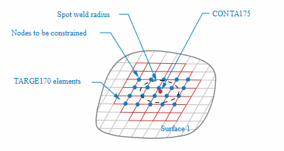
Contact Pairs: Two node-to-surface contact pairs are created for each spot weld set. One pair is for spot weld surface 1 and the other is for surface 2. Each contact pair has only one contact element, CONTA175, which is defined by the associated spot weld node. The target elements (TARGE170) are formed by a group of surface nodes lying within the region of the search radius. The program creates an independent real constant ID for each contact pair, and proper contact and target element type IDs. The following corresponding contact element key options are set by the program: KEYOPT(2) = 2, KEYOPT(12) = 5. For
ICTY=NTOS, target elements KEYOPT(5) = 4 is set for defining the force-distributed constraint type. ForICTY=NTS2, target elements KEYOPT(5) = 7 is set for defining the rigid surface constraint type.Force-distributed constraint equations (
ICTY=NTOS): For each contact pair, the program internally forms force-distributed constraint equations that distribute the internal forces of the spot weld node (that is, the contact node) to the surface nodes (that is, the target nodes) lying within the region of the spot weld radius. This includes all elements that fall entirely or partially within the radius (see Figure 12.11 below). In other words, it couples the motion of certain surface nodes to the motion of the spot weld node (in an average sense). There are six constraint equations generated for each spot weld surface (that is, each contact pair).Rigid surface constraint equations (
ICTY=NTS2): For each contact pair, the program internally forms rigid surface constraint equations between the spot weld node (that is, the contact node) to the surface nodes (that is, the target nodes) lying within the region of the spot weld radius. This includes all elements that fall entirely or partially within the radius.Beam element: A beam element is created to connect surface 1 and surface 2. The two beam end-nodes are the pilot nodes generated at node 1 and node 2 (see Figure 12.12). The spot weld set can be rigid or deformable.
By default, the program creates a rigid beam element (MPC184 with KEYOPT(1) = 1 and KEYOPT(2) = 1) to represent a rigid spot weld. If the currently defined element type ID points to an MPC184 element type with suitable key options, the program uses that element type to define the rigid beam. Otherwise, it generates a new MPC184 element type ID.
If the currently defined element type is MPC184 with KEYOPT(1) = 18 spot weld, the program assumes the spot weld set is deformable and creates a joint element. In this case, you must input the material properties with the MP command, and use the SECTYPE and SECDATA commands to define joint properties.
However, if the currently defined element type is BEAM188 with a solid circular cross-section, the program assumes the spot weld set is deformable and a BEAM188 element is created. In this case, you must input the material properties with the MP command and define the geometry of the beam section using the SECTYPE and SECDATA commands (see Example 12.1). Generally, BEAM188 is capable of handling a short beam situation.
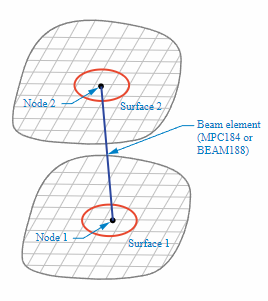
For best results, do not use existing surface nodes as spot weld nodes. Define independent spot weld nodes slightly above or below the surfaces. For instance, in Figure 12.12, Node 1 should be define slightly above Surface 1, and Node 2 should be defined slightly below Surface 2.
SWLIST does not support listing spot welds that have the node-to-surface configuration.
SWDEL does not support deleting spot welds that have the node-to-surface configuration.
In some large assembly models (for example, automobile
applications), multiple spot welds are required to fasten two or more surfaces. You
can easily define multiple spot welds through multi-layered surfaces with just one
SWGEN command by providing a nodal component group name or
element component group name to the SND1 field. This is
only supported in the node-to-surface (NTOS or
NTS2) configuration of spot welds. Multiple surfaces can
be added to the spot weld by providing a component group name in the
NCM1 field. The component group of multiple surfaces must
be defined using the CMGRP command prior to the
SWGEN. No SWADD command is needed. The maximum
number of surfaces allowed for each spot weld set is 8.
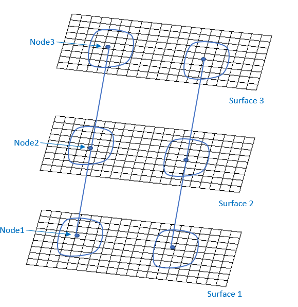
For each new surface, the program creates a new spot weld
node, a new contact pair, and a new beam element (see Figure 12.13). The location of the new node is determined by
projecting of one of the closest existing spot weld nodes onto the newly added
surface along the spot weld projection direction. The new node-to-surface contact
pair contains the new spot weld node as a single contact node in the pair, and
surface nodes within the range of the search radius
(SHRD) specified on the SWGEN command.
The search radius defaults to 4 times the spot weld radius
(SWRD) defined for the basic spot weld set. Each new
contact pair will create force-distributed or rigid surface constraint equations
internally. A new beam is created to link the new surface to the closest existing
surface through the spot weld nodes.
You can use a predefined set of nodes to define multiple spot welds between two or
more surfaces as a multi-layered spot weld. The nodal component group consists of
predefined nodes as the first node of each spot weld. When you use a nodal component
group for SND1, the SND2 argument
is ignored, and the second node is generated automatically. All other
SWGEN command arguments are used as described in Creating a Basic Spot Weld Set with SWGEN.
For each spot weld, the program determines the actual location for the spot weld
nodes by first projecting node 1 onto the nearest surface
(NCM1 on SWGEN) along the spot weld
projection direction. It then generates all the components of the spot weld set,
including a beam element (rigid MPC184 beam or deformable
MPC184 -spot weld / BEAM188) and
two node-to-surface MPC contact pairs (which are force-distributed or rigid-surface constraints). For
more information, see The Components of a Spot Weld.
The name you input for Ecomp represents the component
group consisting of all the multiple spot welds. The SWLIST and
SWDEL commands are not supported for the node-to-surface
configuration. You may use CMPLOT to plot all the spot
welds.
In general, the node-to-surface configuration of spot welds is useful for generating multiple spot welds with fewer contact pair definitions. The software generates contact pairs which consist of multiple contact elements (CONTA175) at each spot weld node and target elements (TARGE170) at spot weld surfaces. Multiple rigid MPC184 beam, deformable BEAM188 beam, or joint elements are generated between the spot weld nodes.
Multiple surfaces can be added to the spot weld by providing a component group
name in the NCM1 field. You must define the component
group of multiple surfaces using the CMGRP command prior to the
SWGEN. No SWADD command is needed. The maximum
number of allowable surfaces for each spot weld set is 8. For each new surface, the
program creates a new spot weld node, a new contact pair, and a new beam element.
The location of the new node is determined by projecting one of the closest existing
spot weld nodes onto the newly added surface along the spot weld projection
direction. The new node-to-surface contact pair contains the new spot weld node as a
single contact node in the pair, and surface nodes within the range of the search
radius (SHRD) specified on the SWGEN
command. The search radius defaults to 4 times the spot weld radius
(SWRD) defined for the basic spot weld set. Each new
contact pair will create force-distributed or rigd surface constraint equations
internally. A new beam is created to link the new surface to the closest existing
surface through the spot weld nodes.
In the example command below, four surfaces are added to a spot weld set named
SWELD1. The first component group
swarea is created from four nodal components of surfaces by
the CMGRP command. Then this component group name is provided at
the field of NCM1 in the SWGEN
command. The NCM2 field is ignored.
cmgr,swarea,ar1,ar2,ar3,ar4
NSEL,S,,,nd21
NSEL,a,,,nd6
NSEL,a,,,nd5
NSEL,a,,,nd4
CM,ndSPot,NODE
swgen,SWELD1,swrd,swarea,,ndSpot,,shrd,,,,,ntos
You can use predefined sets of joint or beam elements to define multiple spot
welds between two or more surfaces as multi-layered. An element component group
consists of predefined joint/beam elements to use for
SND1 (the SND2 field is
ignored). All other SWGEN command arguments are used as described
in Creating a Basic Spot Weld Set with SWGEN.
For each spot weld, the program determines the actual
location for the spot weld nodes by first projecting node 1 of element onto the
nearest surface (NCM1 on SWGEN) along
the spot weld projection direction. It then generates all of the components of the
spot weld set, including two node-to-surface MPC contact pairs (which are force-distributed or rigid surface constraints).
For more information, see The Components of a Spot Weld.
The name you input for Ecomp represents the component
consisting of all the multiple spot welds. The SWLIST and
SWDEL commands are not supported for the node-to-surface
configuration. You may use CMPLOT to plot all the spot
welds.
In general, the node-to-surface configuration of spot welds is useful for generating multiple spot welds with fewer contact pair definitions. The software generates contact pairs which consist of multiple contact elements (CONTA175) at each spot weld node and target elements (TARGE170) at spot weld surfaces. Multiple rigid MPC184 beam, deformable BEAM188 beam, or joint elements are generated between the spot weld nodes.
Multiple surfaces can be added to the spot weld by
providing a component group name in the NCM1 field. You
must define the component group of multiple surfaces using the
CMGRP command prior to the SWGEN. No
SWADD command is needed. The maximum number of allowable surfaces
for each spot weld set is 8. For each new surface, the program creates a new spot
weld node, a new contact pair, and a new beam element. The location of the new node
is determined by projecting one of the closest existing spot weld nodes onto the
newly added surface along the spot weld projection direction. The new
node-to-surface contact pair contains the new spot weld node as a single contact
node in the pair, and surface nodes within the range of the search radius
(SHRD) specified on the SWGEN command.
The search radius defaults to 4 times the spot weld radius
(SWRD) defined for the basic spot weld set. Each new
contact pair will create force-distributed or rigid surface constraint equations
internally. A new beam is created to link the new surface to the closest existing
surface through the spot weld nodes.
In the example command below, four surfaces are added to a spot weld set named
SWELD1. The first component group
swarea is created from four nodal components of surfaces by
the CMGRP command. Then this component group name is provided at
the field of NCM1 in the SWGEN
command. The NCM2 field is ignored.
cmgr,swarea,ar1,ar2,ar3,ar4
mp,ex,2,2.06E05         ! N/mm^2
mp,nuxy,2,0.3           ! No units
mp,dens,2,785E-08       ! kg/m3
sectype,2,beam,csolid   ! define a cylinder beam
secdata,1               ! beam circular radius = 1 mm

c*** Set BEAM188 as current ETYPE to generate deformable spotweld
et,2,188                ! beam for deformable spotweld.
keyopt,2,3,2            ! quadratic option of beam
type,2
mat,2
secnum,2
esel,s,ename,,188
cm,beam,elem
allsel,all

swgen,SWELD1,swrd,swarea,,beam,,shrd,,,,,ntos
Example 12.1: Multiple Layer and Multiple Location Spot Weld Generation
This example generates 64 spot welds multiple locations across 4 layers of shells using only one SWGEN command. Spot welds are generated automatically between all surfaces using predefined joint element components.


Et,id,184
keyo,mx_etyp,1,18
sectyp,mx_secp,join,spwe
secj,spwe,ratio,0.5   ! default is 0.5
secj,lsys,ijz         ! lsys is default, z axis is from node_i to node_j
esel,s,ename,,184
cm,beam,elem
allsel,all
cmgr,swarea,ar1,ar2,ar3,ar4
swgen,top,swrd,swarea,,beam,,2,,,,,ntos
The table that you input must be a 2D array parameter that defines the first node of each spot weld by either a predefined node number or a geometric node location. If needed, you can also include a spot weld radius for each spot weld.
When you use tabular input for SND1, the
SND2 argument is ignored and the second node is generated
automatically. All other SWGEN command arguments are used as
described in Creating a Basic Spot Weld Set with SWGEN.
For each spot weld, the program determines the actual location for the spot weld
nodes by first projecting node 1 (from the 2D array parameter) onto surface 1
(NCM1 on SWGEN) along the spot weld
projection direction. It then generates all the components of the spot weld set,
including a beam element (rigid MPC184 beam or deformable
BEAM188) and two MPC contact pairs (which are force-distributed or rigid surface
constraints). For more information, see The Components of a Spot Weld.
The name you input for Ecomp represents the component
consisting of all the multiple spot welds. The program also generates multiple
subcomponents that contain the individual spot weld sets and names them by appending
"_n" to the Ecomp name
(Ecomp_1, Ecomp_2, and so on).
Follow these guidelines when creating the array parameter and inputting it to SWGEN:
The first spot weld node number for each spot weld is entered in the first column. Set this to zero if using geometric location to define the node.
The 2nd to 4th columns are X, Y, and Z coordinates of the first spot weld nodes (if no node number is provided in column 1). The program automatically creates the first spot weld node using this location.
The 5th column can be used to define a spot weld radius for each spot weld. If not specified, the spot weld radius defined by
SWRDof SWGEN is used.The input format for the
SND1field of SWGEN is %tabname%, wheretabnameis the name you assigned to the array parameter.
These guidelines are demonstrated in Example 12.2: Tabular Input for Defining Multiple Spot Welds.
Use SWLIST,Ecomp to list all spot
welds of the group and
SWLIST,Ecomp_n
to list an individual spot weld set.
Use SWDEL,Ecomp to delete all spot
welds of the group and
SWDEL,Ecomp_n
to delete an individual spot weld set.
Example 12.2: Tabular Input for Defining Multiple Spot Welds
In this example, the first and third spot welds are defined by specific node numbers. The second and fourth spot welds are defined by geometric location. The tabular input is as follows:
First Spot Weld Node
(SND1) | X-coordinate | Y-coordinate | Z-coordinate | Spot Weld Radius (SWRD) |
|---|---|---|---|---|
| 1000 | 0 | 0 | 0 | 0.5 |
| 0 | 18 | 10 | 0 | 0 |
| 1001 | 0 | 0 | 0 | 0.3 |
| 0 | 36 | 10 | 0 | 0 |
The following command input demonstrates how the table is defined and specified on SWGEN:
*set,nd1,1000
*set,nd3,1001
n,nd1,9,10,0
n,nd3,27,10,0
*dim,swdtable,array,4,5
swdtable(1,1) = nd1,0,nd3,0        ! first node numbers for spot weld position
swdtable(1,2) = 0,18,0,36          ! x-coordinates of first nodes
swdtable(1,3) = 0,10,0,10          ! y-coordinates of first nodes
swdtable(1,4) = 0,0,0,0            ! z-coordinates of first nodes
swdtable(1,5) = .5,0,.3,0          ! Spot weld radius
swgen,Ecomp,SWRD,1,2,%swdtable%,,SHRD
Example 12.3: Automatic Generation of Multiple Spot Welds in a Double Hat Channel Model
In this example of a double hat channel model, 20 spot welds (10 on each side) are generated automatically between the two surfaces by using tabular input. Two tables are defined that provide either predefined node numbers or the geometric locations of the spot welds.

c*** Generate spot weld table for 10 spot welds on right side
*dim,swdtable1,array,10,4
swdtable1(1,1) = 19198,0,19200,19201,19202,19203,19204,19205,0,19207
swdtable1(1,2) = 0,0,0,0,0,0,0,0,0,0
swdtable1(1,3) = 0,7.25,0,0,0,0,0,0,4.93e2,0
swdtable1(1,4) = 0,5.15,0,0,0,0,0,0,5.15,0

c*** Generate spot weld table for 10 spot welds on left side
*dim,swdtable2,array,10,4
swdtable2(1,1) = 19218,19219,0,19221,19222,19223,19224,19225,19226,0
swdtable2(1,2) = 0,0,0,0,0,0,0,0,0,0
swdtable2(1,3) = 0,0,1.33e2,0,0,0,0,0,0,5.53e2
swdtable2(1,4) = 0,0,-5.15,0,0,0,0,0,0,-5.15

*set,bid,85
et,bid,188        ! Use BEAM188 elements to create the spot welds
mat,bid
real,bid
type,bid
secnum,bid
!en,18804,19188,19198
sectype,bid,beam,csolid
secdata,2.5
secoffset,cent

c*** Generate 10 spot welds between top plate & bottom plate on right side
*set,swrd,2.5
*set,shrd,3
swgen,ecomp1,swrd,LS_TOP,LS_BOTTOM,%swdtable1%, ,shrd

c*** Generate 10 spot welds between top plate & bottom plate on left side
swgen,ecomp2,swrd,RS_TOP,RS_BOTTOM,%swdtable2%, ,shrd