


RSYMM
RSYMM, Option, CS,
Axis, NSECT,
CONDVALUE, SVAL,
EVAL, TOLER
Defines symmetry, rotation, or extrusion parameters for the radiosity
method.
-
Option Command options:
CLEAR
—
Deletes all symmetry/extrusion definitions. Other command options are ignored.
DEFINE
—
Defines the symmetry/extrusion definition (default).
STAT
—
Shows the status/listing. Other command options are ignored.
COND
—
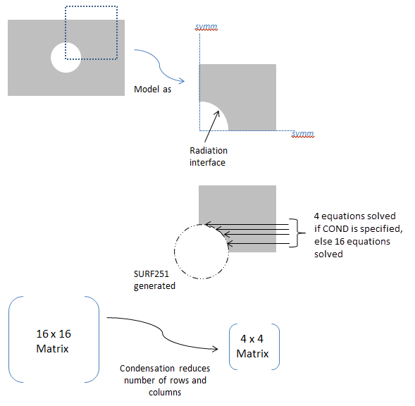
Activates or deactivates condensation for all defined radiation symmetries/extrusions, which reduces the size of the radiosity equation system (see Figure 17: Usage Example:
Option= COND ). Default is off.Note: Condensation via RSYMM,COND is not recommended as the most efficient solution for symmetric models. To best leverage model symmetry to improve efficiency, use view factor condensation via the VFCO command, which condenses the view factor matrix in addition to simplifying the radiosity equations (see Considerations for View Factor Condensation for details).
-
CS Local coordinate system (
 11) as defined using the LOCAL or CS
commands or the global coordinate system (0). For planar reflection, the coordinate system
origin must be on the plane of symmetry (POS) and one of its axes must be normal to the POS.
For cyclic reflection, the coordinate system origin must be coincident with the center of
rotation (COR). Only Cartesian systems are valid.
11) as defined using the LOCAL or CS
commands or the global coordinate system (0). For planar reflection, the coordinate system
origin must be on the plane of symmetry (POS) and one of its axes must be normal to the POS.
For cyclic reflection, the coordinate system origin must be coincident with the center of
rotation (COR). Only Cartesian systems are valid. -
Axis Axis label of the coordinate system (
CS) that is normal to the POS for planar reflection, or label to indicate the type of extrusion. For cyclic reflection, this field must be blank, and it is assumed that the Z axis is aligned with the axis of rotation.X, Y, or Z
—
Planar reflection. For 2D model planar reflections, valid labels are X or Y. For 3D model planar reflections, valid labels are X, Y, or Z.
ZEXT
—
Linear extrusion of a line element in the X-Y plane, in the Z direction, to create 4-noded SURF252 elements.
NSECTindicates how many elements will be created.SVALis the starting Z value, andEVALis the ending Z value.CSmust be 0.CEXT
—
Circumferential extrusion (theta direction) around the global Y-axis. A 2-noded line element in the X-Y plane is extruded to create 4-noded SURF252 elements.
NSECTindicates how many elements will be created.SVALis the starting angle, and EVAL is the ending angle (in degrees). The angles are with respect to the global X-axis.CSmust be 0.(blank)
—
Cyclic reflection.
-
NSECT Number of cyclic reflections to be done, or number of elements in the extrusion direction.
For planar reflection, this field must be 0 or blank.
For cyclic reflection, this field must be ≥ 1 or ≤ -1. Use a positive value if you want the sector angle to be computed automatically. Use a negative value if you want the sector angle to be computed manually. See Notes for details.
-
CONDVALUE Condensation key. Valid only when
Option= COND.ON
—
Activates condensation in the radiosity solver for all defined radiation symmetries/extrusions.
OFF
—
Deactivates condensation in the radiosity solver for all defined radiation symmetries/extrusions (default).
-
SVAL,EVAL Starting and ending Z values (if
Axis= ZEXT) or angle values (ifAxis= CEXT) used for the extrusion. Not used for planar or cyclic reflection.-
TOLER Tolerance dimension used when generating radiosity surface elements (SURF251/SURF252) for planar or cyclic reflection. Defaults to 1.E-7 for planar reflection and 1.E-5 for cyclic reflection. If
TOLERis blank or less than or equal to zero, the default tolerance value is used. If you encounter an warning stating that the planar (or cyclic) symmetry surface intersects the initial patch and the symmetric radiation surfaces are not created as expected, increaseTOLERto a positive number larger than the default value. Not used for extrusion (ZEXT and CEXT).Note: Increase
TOLERwith caution to allow only small offsets. Too large an offset can cause view factor errors.
Notes
The RSYMM command is used to define the plane of symmetry (POS) for planar reflection or the center of rotation (COR) for cyclic reflection. It can also be used to set parameters for a linear or circumferential extrusion. The input provided on this command is used to generate radiosity surface elements (SURF251/SURF252) when the RSURF command is issued.
The RSYMM command must be issued before RSURF, and it may be issued multiple times to have more than one planar/cyclic reflection or extrusion. The RSURF command processes RSYMM commands in the order they are issued.
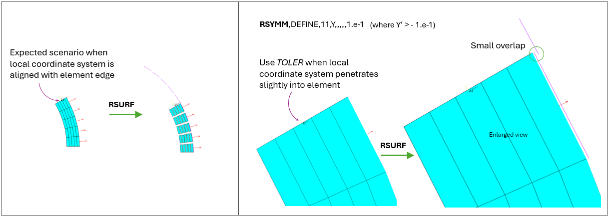
For planar reflection, you must define a local coordinate system (  11) with its origin on the POS. One of its axes
(
11) with its origin on the POS. One of its axes
(Axis) must be aligned so that it is normal to the plane. If possible,
use the existing global coordinate system (0). A small amount of
offset is permissible in cases where the local coordinate system, CS,
slightly penetrates inside the surface of an element. Increasing the tolerance
(TOLER) will allow the symmetry surfaces to be generated with a
greater overlap. Planar reflected nodes can be created provided that the x-coordinates, x′,
in the local system, CS, of all reflected nodes
satisfy the equation: x′ > -TOLER. Alternatively, y′ >
-TOLER, or z′ > -TOLER, depending on
which coordinate is designated as Axis. See Figure 10: Usage Example: Planar Reflection with TOLER for an example of TOLER
usage.
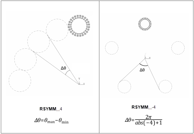
For cyclic reflection, NSECT is used as follows:


where θmax and θmin are computed
internally based on the location of the RDSF (surface-to-surface radiation) flagged surfaces. See
Figure 11: Usage Example: Positive and Negative NSECT Values for an example of NSECT
usage.
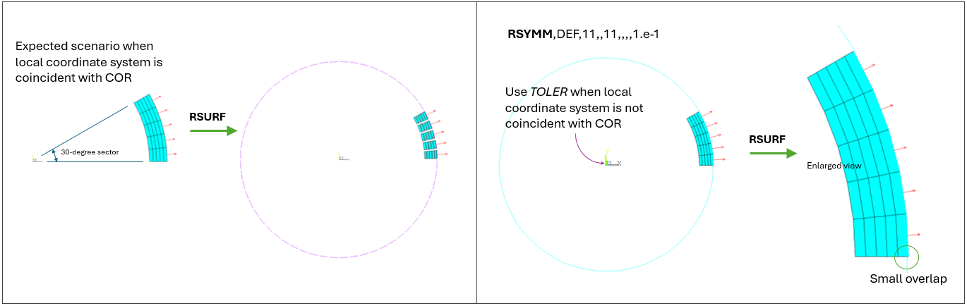
For cyclic reflection, you must define a local coordinate system (  11) with its origin coincident with the COR. Reflections occur about the local
Z-axis in the counterclockwise direction. You must align the Z-axis properly. If possible, use
the existing global coordinate system (0). A small amount of offset
is permissible in cases where the local coordinate system is not coincident with the COR.
Cyclically reflected nodes/elements can be created provided that the sector angle (in radians)
in the local system,
11) with its origin coincident with the COR. Reflections occur about the local
Z-axis in the counterclockwise direction. You must align the Z-axis properly. If possible, use
the existing global coordinate system (0). A small amount of offset
is permissible in cases where the local coordinate system is not coincident with the COR.
Cyclically reflected nodes/elements can be created provided that the sector angle (in radians)
in the local system, CS, satisfies the equation:  *(
*(NSECT+1)/2*𝛑) – 1.0 <
TOLER. See Figure 12: Usage Example: Cyclic Reflection with TOLER for an example
of TOLER usage.
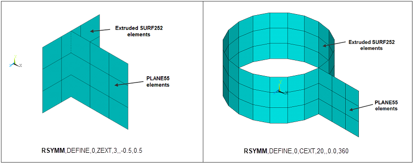
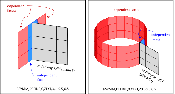
For linear or circumferential extrusion
(Axis = ZEXT or CEXT), you must ensure that the extruded area matches
the area of the underlying element; otherwise, the results may not be correct. For example, in
the case of PLANE55 elements with a planar depth = 10, use
Axis = ZEXT and set SVAL and
EVAL such that EVAL -
SVAL = 10. Likewise, for axisymmetric
PLANE55 elements, use Axis = CEXT and set
SVAL and EVAL such that
EVAL - SVAL = 360. You must also issue
V2DOPT,1 for the axisymmetric case. See Figure 13: Usage Example: Extrusions with Axis = ZEXT and CEXT for
extrusion examples.
The Axis= ZEXT and CEXT options are not
valid for SHELL131 and SHELL132
elements.
New surface elements generated by the RSYMM command inherit the properties of the original elements.
For 2D axisymmetric models, RSYMM can be used only for symmetrization in the YR plane. It cannot be used for the theta direction. Use V2DOPT in that case.
For 2D axisymmetric YR models, the newly-generated nodes can have only positive X coordinates.
Considerations for View Factor Condensation
View factor condensation via the VFCO command is the recommended method to improve solution efficiency for models with symmetry, which are defined with the RSYMM command.
When the RSYMM command is used, it implies that some radiation facets (SURF251 or SURF252) created by the RSURF command will be a reflection of others. By definition, radiation facets with an underlying solid element are independent facets. Dependent facets are copies of the independent facets having the same dimensions but at different locations. The following figures illustrate solid elements (grey) and independent (blue) and dependent (red) facets for models with different types of symmetry. View factor condensation improves efficiency by condensing the view factor matrix to calculate view factors only for independent facets (View Factor Matrix for a Model with Symmetry) and simplifying the radiosity equations to solve only for the independent radiosity flux (Radiosity Equations Simplified for Models with Symmetry in the Theory Reference). For an illustrative example, see Example of a 3D Open Enclosure with Symmetry: Radiation Analysis with Condensed View Factor Calculation in the Thermal Analysis Guide.
Figure 14: Independent and Dependent Facets in a Model with Planar Symmetry Employing View Factor Condensation

Figure 15: Independent and Dependent Facets in a Model with Cyclic Symmetry Employing View Factor Condensation
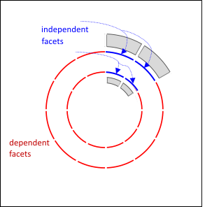
Figure 16: Independent and Dependent Facets for a Model Built by Extrusions Employing View Factor Condensation
Although it is not the recommended method, the following figure illustrates condensation via RSYMM,COND. The efficiency gains by condensation via RSYMM,COND are less than those obtained with view factor condensation via the VFCO command, which reduces the view factor matrix in addition to simplifying the radiosity equations, as described in View Factor Matrix for a Model with Symmetry and Radiosity Equations Simplified for Models with Symmetry in the Theory Reference.
Distributed-Memory Parallel (DMP) Restriction — This command is not supported in a DMP solution.