You can define the Reference Direction through Rosettes or tabular values. For a single element, the Reference Direction is determined by a projection of the Rosette’s X axis onto the element. For simple shapes and scenarios, a single Rosette can be sufficient for the Reference Direction definition. For more complex shapes (such as U-profiles) or a variation of the Reference Direction, select multiple Rosettes for a single OSS. For an example of multiple Rosettes, see Figure 2.74: Reference Direction of a Bonding Laminate Defined by Two Rosettes and a Minimum Angle Selection Method. Using multiple Rosettes requires utilizing the Selection Method to determine which Rosette is applicable to the location of the OSS. The Selection Method offers the following algorithms:
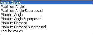
Ansys Classic: Coordinate system is projected on the elements as defined in Ansys (see Coordinate Systems).
Maximum Angle: Coordinate system in which the Z direction has the maximum angle with the element orientation defines the Reference Direction of the Oriented Selection Set.
Maximum Angle Superposed: Same as Maximum Angle but all the chosen coordinate systems are considered and weighted by the maximum difference angle direction.
Minimum Angle: Coordinate system in which the Z direction has the minimum angle with the element orientation defines the Reference Direction of the Oriented Selection Set. (default)
Minimum Angle Superposed: Same as Minimum Angle but all the chosen coordinate systems are considered and weighted by the minimum difference angle direction.
Minimum Distance: Nearest coordinate system of the element defines the Reference Direction of the Oriented Selection Set
Minimum Distance Superposed: Same as Minimum Distance but all the chosen coordinate systems are considered and weighted by the distance to the element.
Tabular Values: Interpolated from the values put in a Look-Up Table. The table must include the location values and a direction column.
Note: If the program is unable to determine an element’s reference direction, it automatically switches to an alternative computation method. For instance, the determination would fail when the X axis of a rosette if perpendicular to the element, making it unable to project the reference direction. In such cases, review the reference directions of the affected OSS and, if necessary, update their definitions. The program issues a warning whenever the alternative computation method is used.
The bonding laminates of the T-Joint example are a case where a Minimum Angle Selection Method is suitable.
Figure 2.74: Reference Direction of a Bonding Laminate Defined by Two Rosettes and a Minimum Angle Selection Method
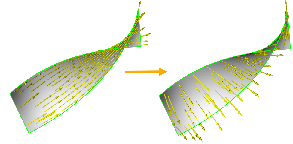
Reference Directions Perpendicular to Edges
Edge-wise Rosettes
can define a Reference Direction along an edge as
shown in the left model in Figure 2.75: Reference Directions Along an Edge and
Perpendicular to an Edge.
To create a Reference Direction perpendicular to an
edge as shown in the right model, you may use the
same Rosettes and set the Rotation
Angle to 90.0
degrees as shown below.

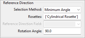
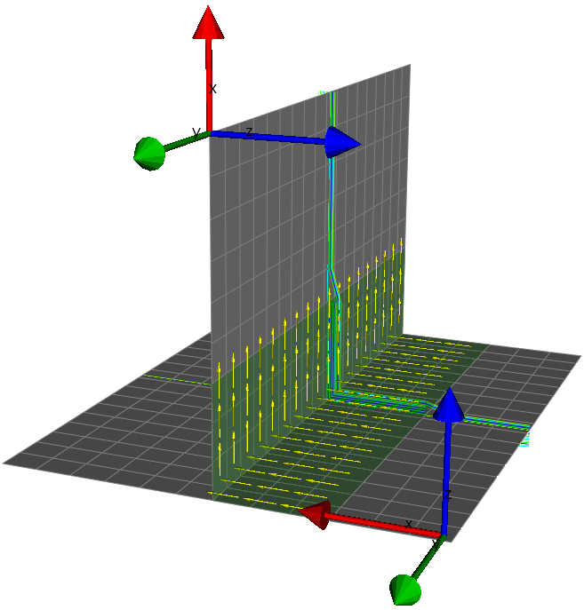
Axial Reference Directions
You may also use Rotation Angle to define a Reference
Direction parallel to the axis of an axisymmetric
structure as shown in Figure 2.76: Axial Reference Direction. In this case,
define the initial Reference Direction using a
cylindrical Rosette and rotate it by
90 degrees as shown
below.