Global Postprocessing
In general, the global solution of all parts can be viewed in the Workbench Mechanical application or Mechanical APDL. Analyzing the results of a multi-part assembly considering solid bodies is also possible in the Mechanical application. Specifically, the results are accessible directly in the analysis system, which must be associated with an ACP (Pre) system. The postprocessing functionality for solid models made in the ACP application enables the mapping of ply-wise results onto the reference surface of the solid model. This functionality ensures that failures occurring inside the laminate can be observed and investigated.
Mechanical Application Postprocessing
Postprocessing layered solid models in the Mechanical application supports creation of stress and strain plots in a similar method as a composite shell model. In the case where a solid model is created in the ACP (Pre) system and a solution is available for the solid model, failure analysis can be investigated in a few different ways.
In the Mechanical application, from the Solution context tab, insert a Composite Failure Tool from the Toolbox icon. In the details of the Composite Failure Tool, define the Reinforced Ply Criteria desired for your failure assessment. For example, Maximum Stress and Puck are activated and configured in the following figure.
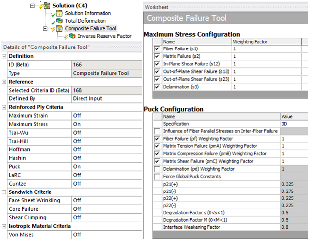
Next, in the Composite Failure Tool, scope the Inverse Reserve Factor, Safety Factor, or Safety Margin results item to the solid body geometry containing the mesh with the ACP (Pre) composite definition. The following methods use Inverse Reserve Factor failure postprocessing.
Method 1: Failure Evaluation for All Elements
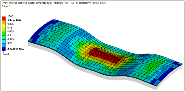
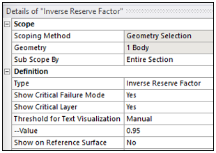
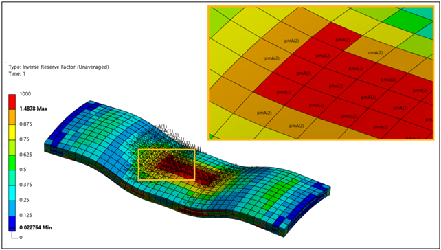
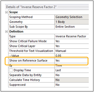
In the details window of the failure results item, set the Sub Scope By to the Entire Section and show both the critical failure mode and critical layer. The worst-case failure criteria value is displayed by color contour and the text label describes the critical mode and layer (In parentheses). The layer identification is helpful if the solid elements contain more than one ply or layer. Also, optionally set the Threshold for Text Visualization to control the level at which you display the text on critical elements.
|
|
|
|
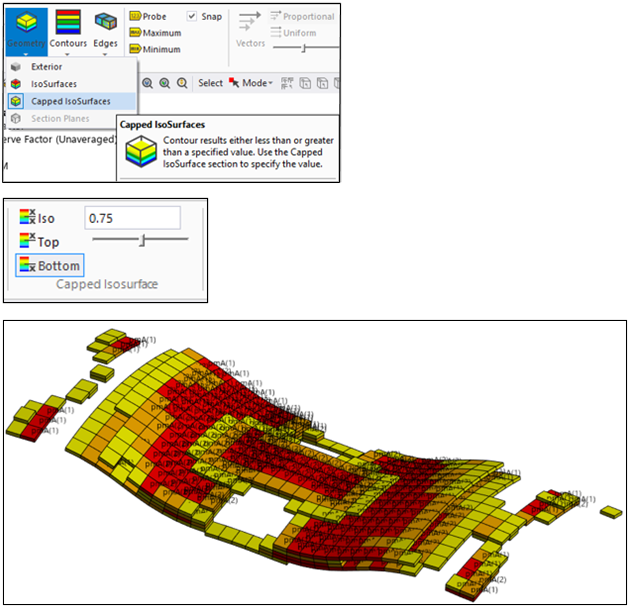
Additionally, on the Results ribbon tab, you can set Capped Isosurfaces with Bottom filtering to display only those elements above a user defined threshold of the Inverse Reserve Factor.
Method 2: Failure Evaluation for Entire Stackup
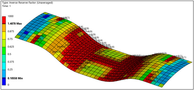
Since it may be difficult to identify the worst-case location if it occurs inside the composite part, a concise summary for the entire stackup is helpful. In the details window of the failure results item, set Show on Reference Surface to Yes. This will summarize and display worst-case results in color contour and present the critical failure mode and layer of the entire stackup. This contour and text display will be projected on the reference shell mesh summarizing the results for the entire laminate and hide the solid mesh to create a more concise visualization.
|
|
|
|
Method 3: Failure Evaluation for a Single Ply
Individual ply failure results can be shown by changing the Sub Scope By definition to Ply in the details window of the desired results item. You can then select the desired engineering ply item in the Imported Plies laminate definition.
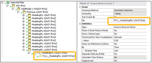
This will then display a contour plot containing that ply's results shown on the solid elements containing that ply and display the rest of model as semi-transparent.