The component controls allow you to specify input data and view the results values for the pump impeller and volute.
You can use either SI or Imperial units for the input data and results. Note that the standard unit systems are sometimes modified to reflect commonly used units in pump design. For example, rotational speed is specified in rpm and not in rad/s.
The Duty frame contains all the data needed to define the duty for which a pump is to be designed:
Rotational speed
This setting controls the design point rotational speed of the machine (rpm).
Volume flow rate
This setting controls the delivery volumetric flow rate of the pump. The volume of flow that passes through the impeller is normally higher than this because some of the flow leaks past the impeller back into the inlet eye. The specified volumetric efficiency is used to account for this leakage.
Density
This setting is used to determine the operating fluid. The default value of 1000 kg/m^3 is for water.
Head rise
This setting controls the total dynamic head rise required of the pump at the design point. The head rise is the sum of the static head rise and the velocity head rise. For a fixed volume flow rate, the velocity head is determined by the area of the aperture. In the case of a centrifugal pump, a smaller inlet gives a larger inlet velocity head and vice versa. If the pump has the same inlet and outlet areas, the total dynamic head rise will be equal to the static head rise.
Inlet flow angle
This setting controls the angle of the flow, denoted by
 , at the impeller leading
edge, measured with respect to the tangential direction. The default
value of 90 degrees is for an approach flow without pre-rotation.
When the flow approaches from a plane pipe, you can generally leave
this value at the default of 90°. However, when an upstream inducer
is employed in order to reduce cavitation, you may need to adjust
this value.
, at the impeller leading
edge, measured with respect to the tangential direction. The default
value of 90 degrees is for an approach flow without pre-rotation.
When the flow approaches from a plane pipe, you can generally leave
this value at the default of 90°. However, when an upstream inducer
is employed in order to reduce cavitation, you may need to adjust
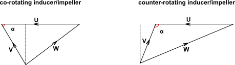
this value.For an inducer that rotates in the same direction as the impeller, the inlet flow angle will be less than 90°. This may happen when the inducer and the impeller are both mounted on the same shaft. Conversely, for a counter-rotating inducer/impeller pair, the inlet flow angle will be greater than 90°.
The inlet swirl angle is treated as a constant value from hub to shroud.
Meridional velocity ratio
This setting is used to describe a linear velocity profile from the hub to the shroud at the leading edge. It sets the gradient of the profile by specifying the ratio of the meridional velocity at the shroud leading edge radius to the meridional velocity at the average leading edge radius.
The default value of 1.1 indicates a larger meridional velocity at the shroud than at the hub. A value of less than 1 indicates a larger meridional velocity at the hub than at the shroud. A value of 1 indicates a uniform meridional velocity distribution.
You may specify the pump efficiencies individually or have Vista CPD calculate them automatically using correlations based on historical data for a range of machine specific speeds.
When you specify individual efficiencies, only three of the four efficiencies may be set, since the efficiencies are related by the following equation:
 | (7–1) |
Hydraulic
The hydraulic efficiency (
 ) results from the reduction in head due
to the pressure loss resulting from the pump hydrodynamic design (for
example, friction losses, turning losses, and so on). This is normally
the most significant of the efficiency components that can be influenced
by the designer. Hydraulic efficiency is calculated from the following
equation:
) results from the reduction in head due
to the pressure loss resulting from the pump hydrodynamic design (for
example, friction losses, turning losses, and so on). This is normally
the most significant of the efficiency components that can be influenced
by the designer. Hydraulic efficiency is calculated from the following
equation: where
 is the ideal head rise and
  is the head loss due to the hydrodynamic design.
There is often a trade-off between peak hydraulic efficiency and a flatter efficiency profile over a wider operating range. Therefore, a pump with a high design point hydraulic efficiency may perform more poorly over the rest of the operating range compared with a pump with a lower design point hydraulic efficiency.
Volumetric
The volumetric efficiency (
 ) results primarily
from the leakage of flow past the impeller back into the inlet eye.
This normally occurs between the shroud ring and the outer casing
of the pump. Therefore, in order to deliver the specified volume of
flow at the outlet, the volume of flow that passes through the impeller
must be increased by this leakage volume. Volumetric efficiency is
calculated from the following equation:
) results primarily
from the leakage of flow past the impeller back into the inlet eye.
This normally occurs between the shroud ring and the outer casing
of the pump. Therefore, in order to deliver the specified volume of
flow at the outlet, the volume of flow that passes through the impeller
must be increased by this leakage volume. Volumetric efficiency is
calculated from the following equation:where
 is the volume of flow delivered at the outlet and
  is the leakage flow.
Pumps designed to have tight performance will have less leakage and therefore a higher volumetric efficiency. However, these designs may be more susceptible to wear, especially when the pumped fluid has a significant suspended solids content. In this case, a "loose" performance pump with a lower volumetric efficiency may be favorable because it will provide a more consistent performance over a longer operating period.
Mechanical
The mechanical efficiency (
 ) results from drag on the rotating component
of the pump due to mechanical friction and viscous friction on the
outside surface of the impeller shroud (disk friction). Disk friction
is the dominant component in the mechanical loss. Mechanical efficiency
is calculated from the following equation:
) results from drag on the rotating component
of the pump due to mechanical friction and viscous friction on the
outside surface of the impeller shroud (disk friction). Disk friction
is the dominant component in the mechanical loss. Mechanical efficiency
is calculated from the following equation:where
 is the shaft input power of the pump and
  is the power lost due to disk friction.
 Pumps designed to have tight performance with smaller clearances will generally suffer more from disk friction effects compared to "loose" performance pumps.
Pump
The overall pump efficiency. As indicated in Equation 7–1, this is the product of the hydraulic, volumetric, and mechanical efficiencies.


To enter the impeller geometry data, select Impeller in the component selection control, and click the Geometry tab.
Shaft minimum diameter factor
The shaft minimum diameter is calculated based on the maximum allowable shear stress of the shaft. The shaft minimum diameter factor is then applied to the resulting value as a factor of safety. The default value of 1.1 represents a 10% increase in the shaft diameter.
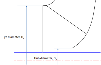
Dhub/Dshaft
This is the ratio of the impeller hub diameter to the shaft diameter. The hub and shaft diameters are shown in Figure 7.7: Hub and Shaft Diameter Locations.

Hub and Meanline
This drop-down menu controls how the leading edge blade angles are calculated at the hub and meanline locations. You can select from three methods using the Hub and Meanline drop-down menu:
Cotangent(default)In this method, the angles are calculated relative to the shroud leading edge blade angle. The angle is calculated as follows:
for the hub, and similarly
for the meanline.
CosineThis method uses a similar approach calculating the angles as follows:
for the hub, and similarly
for the meanline.
User definedThis method allows you to specify the angles directly.
Shroud
The leading edge blade angle at the shroud is defined either indirectly by specifying the incidence angle at the shroud, (default, 0 degrees incidence), or directly by specifying the value of the angle.


This sets the diameter of the impeller at the meanline trailing
edge location. The tip diameter is probably the most important early
decision in the hydraulic design of a centrifugal pump, since the
impeller diameter and the tip speed,  , influence all other dimensions of the
pump hydraulic design and performance characteristics.
, influence all other dimensions of the
pump hydraulic design and performance characteristics.
There are three methods for specifying the tip diameter. You can select from the three methods by using the Tip diameter drop-down menu:
Automatic (using stability factor)(default)A prerequisite for a new pump design is that the head-flow characteristic is stable, that is, continuously rising to zero flow. Unstable head curves may be due to excessive diffusion of the impeller relative velocity at low flows and may also be due to excessive blade shape effect compared with centrifugal effect in head generation.
Impeller diffusion can be defined as:
where
 and
and  are the meanline relative velocities at the inlet
and outlet respectively. Analysis of pump tests show that when
are the meanline relative velocities at the inlet
and outlet respectively. Analysis of pump tests show that when  at pump best efficiency
flow, instability in a head-flow curve at lower flows is very unlikely.
For this condition it can be shown that the tip diameter should be
such that:
at pump best efficiency
flow, instability in a head-flow curve at lower flows is very unlikely.
For this condition it can be shown that the tip diameter should be
such that:
where
 and
and  are the meanline blade
speeds at the leading and trailing edges, respectively, and
are the meanline blade
speeds at the leading and trailing edges, respectively, and  is the meanline tangential flow velocity at the
trailing edge.
is the meanline tangential flow velocity at the
trailing edge.This leads to the definition of the stability factor,
 :
:For a stable head-flow characteristic,
 should be > 0.9. Vista CPD calculates
a value for
should be > 0.9. Vista CPD calculates
a value for  based on the speed of the machine. With
  already established, the tip diameter is specified.
Specify head coefficientIn this method, Vista CPD calculates the tip diameter based on a given head coefficient,
 . This is a non-dimensional parameter that
is useful when the new pump is based on an existing design of known
head coefficient.
. This is a non-dimensional parameter that
is useful when the new pump is based on an existing design of known
head coefficient.The head coefficient is defined by:
User definedThis method allows you to directly specify the tip diameter. This method is useful when the new design is a replacement for an existing machine and the tip diameter is already a constraint. In this case, you should first use the
Automaticmethod to obtain a design close to what is needed, and then you should switch to theUser definedmethod to establish the exact tip diameter needed.


Blade angle
The trailing edge blade angle,
 , is the angle the blade makes with respect to the
tangential direction at the trailing edge as shown in Figure 7.8: Trailing Edge Blade Angle.
, is the angle the blade makes with respect to the
tangential direction at the trailing edge as shown in Figure 7.8: Trailing Edge Blade Angle.
The trailing edge blade angle is a key factor in determining the impeller width at the trailing edge, also called the tip width,
 shown in Figure 7.9: Tip Width. This
is a logical relationship since the exit flow rate is determined by
the meridional velocity and the cross sectional area at that point,
as defined by the usual continuity equation:
shown in Figure 7.9: Tip Width. This
is a logical relationship since the exit flow rate is determined by
the meridional velocity and the cross sectional area at that point,
as defined by the usual continuity equation: At a given rotational speed, a reduction in the blade angle results in a smaller meridional velocity,
 . In order to maintain the flow rate,
  ,
the cross sectional area,
,
the cross sectional area,  , must be increased.
For a fixed impeller diameter,
, must be increased.
For a fixed impeller diameter,  can only be raised
by increasing the tip width,
can only be raised
by increasing the tip width,  . Conversely, increasing the blade angle at a fixed
rotational speed and impeller diameter reduces the tip width.
. Conversely, increasing the blade angle at a fixed
rotational speed and impeller diameter reduces the tip width.
The default value of 22.5 degrees is considered to be a standard design. Studies have shown that increasing the blade angle can lead to an enhanced head rise, but with an associated reduction in hydraulic efficiency.
Rake angle
This is the angle the trailing edge makes with a line perpendicular to the hub surface, also referred to as the blade lean at the trailing edge. Since only the hub and shroud sections are considered in Vista CPD, only straight lean, as opposed to compound lean, is possible.
The default value of 0 degrees is very common in pumps, likely for manufacturing reasons, although a positive rake angle can be used to reduce secondary flows by influencing the distribution of flow in the spanwise (hub to shroud) direction. This approach is more common in centrifugal compressors, but the same mechanism applies to centrifugal pumps.


Number of vanes
The number of blades used in the impeller. A larger number of blades gives greater control over the flow direction in the impeller, but with an increased blockage to flow due to the larger solid to fluid ratio. This will also affect the blade angle and tip width described in Trailing Edge Blade Angles.
As the number of vanes is increased both the tip width,
 , and the relative flow angle
at the trailing edge,
, and the relative flow angle
at the trailing edge,  , are influenced. The plot shown below in Figure 7.10: Influence of the Number of Vanes on Impeller Tip Width and
Relative Flow Angle at the Trailing Edge shows a typical example
of the behavior of
, are influenced. The plot shown below in Figure 7.10: Influence of the Number of Vanes on Impeller Tip Width and
Relative Flow Angle at the Trailing Edge shows a typical example
of the behavior of  and
and  with the variation of the number of vanes.
Figure 7.10: Influence of the Number of Vanes on Impeller Tip Width and Relative Flow Angle at the Trailing Edge
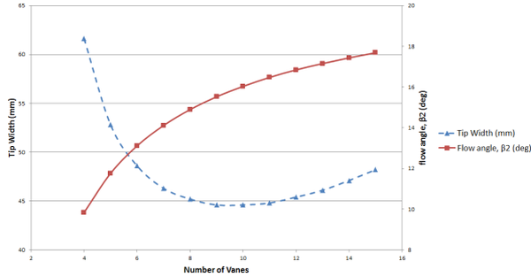
The plot shows how as the number of vanes is increased
 also increases, gradually
becoming closer to the trailing edge blade angle,
also increases, gradually
becoming closer to the trailing edge blade angle,  , because the impeller imposes
greater control on the flow direction. As a consequence of the increase
in
, because the impeller imposes
greater control on the flow direction. As a consequence of the increase
in  the meridional velocity at the trailing
edge,
the meridional velocity at the trailing
edge,  , is also increased. This in turn acts to
reduce the flow area at the trailing edge and, as a result, the tip
width,
, is also increased. This in turn acts to
reduce the flow area at the trailing edge and, as a result, the tip
width,  also decreases for a fixed tip diameter. However,
another effect of increasing the number of vanes is increasing the
blockage to the flow. This increased blockage acts to increase
also decreases for a fixed tip diameter. However,
another effect of increasing the number of vanes is increasing the
blockage to the flow. This increased blockage acts to increase  in order to maintain the flow
area at the trailing edge. Consequently, an increase in the number
of vanes has two competing influences on the tip width of the impeller. Figure 7.10: Influence of the Number of Vanes on Impeller Tip Width and
Relative Flow Angle at the Trailing Edge shows that the influence
of the variation in
in order to maintain the flow
area at the trailing edge. Consequently, an increase in the number
of vanes has two competing influences on the tip width of the impeller. Figure 7.10: Influence of the Number of Vanes on Impeller Tip Width and
Relative Flow Angle at the Trailing Edge shows that the influence
of the variation in  dominates for a low number of vanes, with
the tip width decreasing as the number of vanes is increased. As the
number of vanes increases further, the effects of the blockage to
the flow dominate and the tip width increases.
dominates for a low number of vanes, with
the tip width decreasing as the number of vanes is increased. As the
number of vanes increases further, the effects of the blockage to
the flow dominate and the tip width increases.Thickness/tip diameter
The thickness to tip diameter ratio is a non-dimensional parameter used to define the impeller vane thickness. Increasing the thickness to tip diameter ratio also increases the blockage to flow. This results in a larger tip width although, unlike when increasing the number of vanes, this has no effect of the trailing edge flow angle.
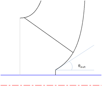
Hub inlet draft angle
The hub inlet draft angle,
 , is the angle between the hub and the horizontal
line at the hub inlet, as shown in
, is the angle between the hub and the horizontal
line at the hub inlet, as shown in Reducing the hub inlet draft angle moves the hub inlet point forward, which results in a smaller hub radius. Conversely, a larger value moves the hub inlet point backward, which results in a bigger hub radius. For low specific speed machines, it is common to use a larger
 , whereas higher specific speed machines
may benefit from a lower
, whereas higher specific speed machines
may benefit from a lower  .
.
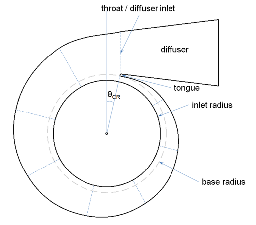
The volute design in Vista CPD is calculated to maintain a constant angular momentum in the scroll, with a small adjustment to account for friction losses at the walls. Starting at the tongue and ending at the throat, the required cross sectional areas are established at 8 equally spaced locations around the scroll and are used to determine the appropriate dimensions of the selected cross section shape. The throat is co-located at the diffuser inlet. The length and exit area of the diffuser section may optionally be specified by the user. The central section of the volute is shown in Figure 7.12: Central Section of the Volute.
The inlet width of the volute is calculated from the sum of the impeller tip width, the hub and shroud solid thicknesses, and the clearances between the rotating impeller and the stationary casing at the hub and at the shroud. This arrangement is show in Figure 7.13: Impeller and Volute Interface Arrangement.
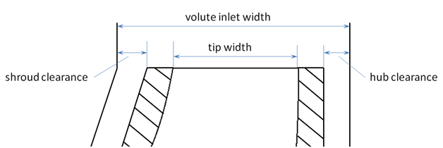
Note that the volute inlet width can often measure twice
as much as the impeller tip width.
The casing rotation,  , is the angle
between the vertical line and the tongue location when viewing the
central section through the volute, as shown in Figure 7.12: Central Section of the Volute. The default value of 14 degrees
is suitable in most cases, but small adjustments may be made to ensure
a smooth transition to the diffuser section.
, is the angle
between the vertical line and the tongue location when viewing the
central section through the volute, as shown in Figure 7.12: Central Section of the Volute. The default value of 14 degrees
is suitable in most cases, but small adjustments may be made to ensure
a smooth transition to the diffuser section.
There are two options for the volute section shape:
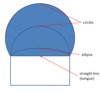
Elliptical/circular
This section type begins as a straight line at the tongue and transitions to an elliptical section thereafter. In the smaller sections, the major axis is fixed by the volute width and the minor axis is adjusted to achieve the desired area. Where the required value of the minor axis would be greater than the value of the major axis, both axes are made equal and the section is then circular.
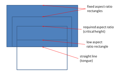
Rectangular
This section type begins as a straight line at the tongue and transitions to a rectangular section. An additional parameter to specify for rectangular sections is the aspect ratio (width/height) at the throat.
Given the volute width, a critical height can be calculated:
where
 is the specified
aspect ratio. This translates to a critical area:
is the specified
aspect ratio. This translates to a critical area:or
Below this critical area, the width of the rectangle is fixed by the volute width and the height is adjusted to achieve the desired cross sectional area with an aspect ratio less than that specified. Above this critical area the aspect ratio of the rectangle is fixed by the value specified and the height and width are adjusted to match the required cross sectional area accordingly.


The exit diameter and length of the diffuser section are calculated to achieve a reasonable rate of diffusion while avoiding stall. To define these settings manually, select the check box next to the setting you would like to define, and enter the desired value in the appropriate box. If the check boxes are cleared, these values will be calculated automatically by Vista CPD.
To view these results, click the Results tab and set the component
selection control to impeller.
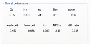
This section presents the overall performance parameters that characterize the pump impeller.
Specific speeds:
 (non-dimensional),
  (US units),
  (European units)
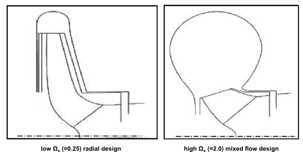
Specific speed is a number that loosely defines the geometric shape of a pump. For example, a low
 , high head pump would have a narrow radial
impeller and a small section volute throat. A higher
, high head pump would have a narrow radial
impeller and a small section volute throat. A higher  , lower head, mixed
flow design would involve a wider, more conical impeller and the volute
throat area would be comparatively larger.
, lower head, mixed
flow design would involve a wider, more conical impeller and the volute
throat area would be comparatively larger.Pump efficiency reaches a peak value when
 is close to 1.0. It may be possible to
arrange the pump design duty or pump speed to take advantage of this
fact.
is close to 1.0. It may be possible to
arrange the pump design duty or pump speed to take advantage of this
fact.Equivalent forms of
 which are commonly used in the US and in
Europe are also included here for convenience. They can be related
to
which are commonly used in the US and in
Europe are also included here for convenience. They can be related
to  simply as:
and
A value of
 between 0.3 and 0.8 indicates a radial
flow impeller, a value of
between 0.3 and 0.8 indicates a radial
flow impeller, a value of  between 1.0 and 2.5 indicates a mixed flow
impeller, and a value of
between 1.0 and 2.5 indicates a mixed flow
impeller, and a value of  above 3.5 indicates an axial flow impeller.
The specific speed has a significant influence on pump shape. A low
 pump has a narrow radial flow impeller
and the outlet diameter is significantly larger than the inlet diameter.
A high
pump has a narrow radial flow impeller
and the outlet diameter is significantly larger than the inlet diameter.
A high  pump has a mixed flow impeller and the
outlet diameter is only slightly larger than the inlet diameter.
pump has a mixed flow impeller and the
outlet diameter is only slightly larger than the inlet diameter.The specific speed also has a significant influence on the shape of the pump performance curve. A low
 , radial flow impeller
pump has a head/flow curve with a low head rise to zero flow. The
pump power/flow curve usually rises continuously from about 50% at
zero flow. A medium
, radial flow impeller
pump has a head/flow curve with a low head rise to zero flow. The
pump power/flow curve usually rises continuously from about 50% at
zero flow. A medium  , mixed flow impeller pump has a more steeply
falling head/flow curve and the power may be at its maximum at the
pump design flow.
, mixed flow impeller pump has a more steeply
falling head/flow curve and the power may be at its maximum at the
pump design flow.Suction specific speed,

Suction specific speed is a non-dimensional parameter that can be useful in the evaluation of pump cavitation performance.
where
 and
and  are taken at the highest efficiency, or design point,
of the impeller.
are taken at the highest efficiency, or design point,
of the impeller.Note that Vista CPD uses the non-dimensional form of
 . Similar to the specific
speed, alternative forms are also in use for the US and European unit
systems. Since the units for
. Similar to the specific
speed, alternative forms are also in use for the US and European unit
systems. Since the units for  and head are the same, the same conversion factors
shown above also apply.
and head are the same, the same conversion factors
shown above also apply.For overhung impeller volute pumps, with
 for
3% head loss,
for
3% head loss,  indicates the following
performances:
indicates the following
performances:1.5 indicates generally poor cavitation performance
2.5 indicates reasonable cavitation performance
4.0 indicates good cavitation performance
Above 4.0 is exceptional (possible enlarged impeller inlet area)
Power
The shaft power of the impeller. This is defined as a combination of the hydraulic power and the overall pump efficiency:
where
 is the impeller mass flow rate,
  is the head rise and
  is the overall pump efficiency.
Head Coefficient,
 (head coeff)
Where the characteristics of an established pump are known, it is common to scale this design to produce a family of geometrically similar pumps which operate at different speeds. A key parameter that remains constant through such a scaling is the head coefficient. This is a measure of the energy transfer to the fluid (sometimes called the energy transfer coefficient) and is defined as:
where
 is the head rise, and
  is the blade speed at the meanline trailing
edge location.
is the blade speed at the meanline trailing
edge location.Flow coefficient,
 (flow coeff)
Similar to the head coefficient, the flow coefficient remains the same for geometrically similar pumps. As the name suggests, this is a measure of the flow rate through the pump and is defined as
where
 is the impeller volume flow rate,
  is the rotational speed,
and
is the rotational speed,
and  is the meanline tip diameter.
Stability factor,

The stability factor is a measure of how stable the pump's performance characteristic curve is likely to be. A value of less than 0.9 at the design point indicates that the head curve may fall as the flow rate approaches zero, a so-called unstable characteristic. The stability factor is defined as
where
 and
and  are the meanline blade speeds at the leading and
trailing edges respectively, and
are the meanline blade speeds at the leading and
trailing edges respectively, and  is the tangential velocity at the meanline trailing
edge location.
is the tangential velocity at the meanline trailing
edge location.Net positive suction head required,

If the pressure at a point in the flow field drops below the vapor pressure of the liquid, the liquid will vaporize, a process known as cavitation. As the vapor bubble moves back into a region of pressure higher than the vapor pressure, the bubble will collapse as it reverts back to liquid form. This is a violent process due to the large density change involved which causes noise and, above all, damage to pumps.
In centrifugal pumps, the liquid accelerates into the eye of the pump causing the pressure to drop. If there is insufficient head at the eye to accommodate this local pressure drop then the pump will cavitate. The
 is the level of head required at the impeller eye
in order to avoid significant noise and damage due to cavitation.
is the level of head required at the impeller eye
in order to avoid significant noise and damage due to cavitation.It is possible to reduce the
 by increasing the eye diameter to reduce the acceleration
effect. However, this increases the risk of recirculation at the shroud
inlet, which itself can result in severe flow oscillations and cavitation.
A common approach to mitigate against cavitation, where insufficient
by increasing the eye diameter to reduce the acceleration
effect. However, this increases the risk of recirculation at the shroud
inlet, which itself can result in severe flow oscillations and cavitation.
A common approach to mitigate against cavitation, where insufficient  is available, is the addition
of an inducer ahead of the impeller inlet to provide the extra head
required.
is available, is the addition
of an inducer ahead of the impeller inlet to provide the extra head
required.Diffusion Ratio
The diffusion ratio is defined as
where
 and
and  are the meanline relative velocities at the inlet
and outlet respectively. Analysis of pump tests show that when
are the meanline relative velocities at the inlet
and outlet respectively. Analysis of pump tests show that when  at highest efficiency
flow, instability in a head-flow curve at lower flows is very unlikely.
Consequently, a value of diffusion ratio close to zero is desirable,
a value greater than 0.25 is considered high.
at highest efficiency
flow, instability in a head-flow curve at lower flows is very unlikely.
Consequently, a value of diffusion ratio close to zero is desirable,
a value greater than 0.25 is considered high.


This section describes the calculated dimensions, angles and velocities at the impeller leading edge.
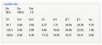
Basic Dimensions
The hub diameter, Dh, and the eye diameter, De, are the inlet diameters at hub and shroud as indicated in
The vane thickness, Thk, is the normal thickness of the vane calculated from the specified thickness to diameter ratio.
Detailed Parameters
The following parameters are calculated at the hub, meanline, and shroud sections, and are listed in table format:
Diameter,

Tangential velocity,

Meridional velocity,

Blade speed,

Flow relative velocity,

Blade angle,

Relative flow angle,

Incidence,

Here both the blade angles,
 and the
relative flow angles,
and the
relative flow angles,  are measured relative
to the tangential direction, similar to the specification of the inlet
flow angle (see Figure 7.8: Trailing Edge Blade Angle). The incidence
is simply calculated as
are measured relative
to the tangential direction, similar to the specification of the inlet
flow angle (see Figure 7.8: Trailing Edge Blade Angle). The incidence
is simply calculated as  and is presented
for convenience.
and is presented
for convenience.
This section describes the calculated parameters at the impeller trailing edge.
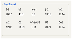
Tip diameter,

Tip width,
 (see Figure 7.9: Tip Width)
Lean angle (rake),

Relative flow angle,

Flow relative velocity,

Absolute flow angle,

Flow absolute velocity,

Slip factor,

Blade speed (tip speed),

Flow tangential velocity,

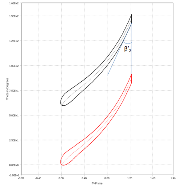
The slip factor is a non-dimensional parameter which indicates
the degree to which the flow is expected to deviate from the blade. Figure 7.16: Exit velocity triangles with slip (red) and without slip (black) shows the exit velocity triangles
for both the hypothetical case where the flow angle is the same as
the blade exit angle,  , and the true case with the flow angle of
  .
.
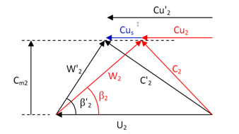
The slip velocity,  , is defined as the difference between the
no-slip tangential velocity,
, is defined as the difference between the
no-slip tangential velocity,  , and the true tangential velocity,
  . The slip
factor,
. The slip
factor,  , is defined as the ratio of the slip velocity
to the trailing edge tip speed,
, is defined as the ratio of the slip velocity
to the trailing edge tip speed,  :
:

To view these results, click the Results tab and set the component
selection control to Volute.
This section describes some key dimensions defining the volute geometry.
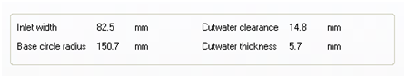
Inlet width
For details on how the volute inlet width relates to the impeller tip width, see Figure 7.13: Impeller and Volute Interface Arrangement.
Base circle radius
The base circle radius is the radius of the circle that touches the tongue (or cutwater). It is shown in Figure 7.12: Central Section of the Volute.
Cutwater clearance
The cutwater clearance is the distance between the impeller tip and the volute tongue, calculated as the difference between the base circle radius and the meanline impeller tip radius.
Cutwater thickness
The cutwater thickness is the thickness of the tongue at the point where it meets the base circle.
This section presents the geometrical properties of the calculated volute cross sections in tabular form. The data displayed varies slightly depending on whether the volute sections are elliptical/circular or rectangular. Figure 7.17: Sample Elliptical/circular Cross-section Data shows an example of elliptical/circular cross section data, and Figure 7.18: Sample Rectangular Cross-section Data shows an example of rectangular cross section data.
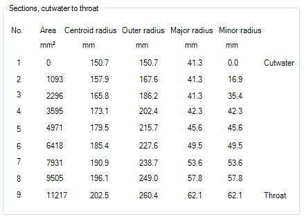
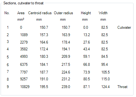
The areas, centroid radii, and outer radii of the cross sections are shown for both elliptical/circular and rectangular section types.
For the elliptical/circular section type the major and minor axes of the ellipses are shown. When the major and minor axes are equal the section is circular.
For the rectangular section type the height and width is listed. In the sections where the width is equal to the volute inlet width, the aspect ratio (height/width) of the section is usually less than the value specified in the geometry panel, (except where the height equals the critical height). When the width exceeds the volute inlet width, the required aspect ratio is met.
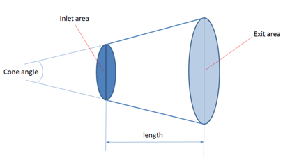
This section describes the basic dimensions of the diffuser section of the volute.
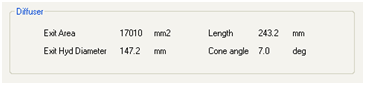
The exit hydraulic diameter is calculated as the diameter of the equivalent circular section with an area equal to the calculated exit area. The cone angle is calculated as the angle between the sloping sides of the equivalent circular based conic frustum, as shown in Figure 7.19: Equivalent Conic Frustum Diffuser.