


This tutorial includes:
This tutorial teaches you how to:
Create a mesh involving tandem vanes using a topology template.
As you work through this tutorial, you will create a mesh for a blade set of a radial machine component that has tandem vanes. A typical blade set is shown by the black outline in the figure below.
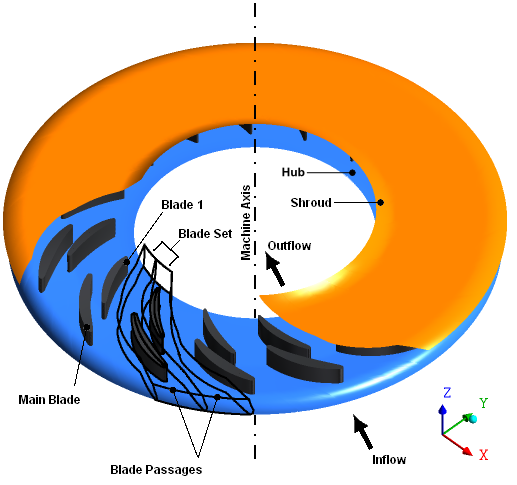
The component has 16 blade sets, each containing one main blade and one tandem vane. Within the blade passages, the maximum diameter of the shroud is approximately 52.2 cm.
You will begin by loading the geometry from a BladeGen.inf file. You will then select a topology template and set the mesh density.
If this is the first tutorial you are working with, it is important to review Introduction to the Ansys TurboGrid Tutorials before beginning.
Create a working directory.
Ansys TurboGrid uses a working directory as the default location for loading and saving files for a particular session or project.
Download the
tandem.zipfile here .Unzip
tandem.zipto your working directory.Ensure that the following tutorial input files are in your working directory:
BladeGen.inf
shroud.curve
hub.curve
profile.curve
Set the working directory and start Ansys TurboGrid.
For details, see Setting the Working Directory and Starting Ansys TurboGrid.
Click File > Load TurboGrid Init File.
Open
BladeGen.inffrom the working directory.
While TurboGrid can automatically generate acceptable meshes for basic turbomachinery, you may need to specify topology templates for complex blade configurations, such as tandem vanes.
Select the appropriate template as follows:
In the Mesh workspace, open
Topology Set.Set ATM Topology > Method to
Tandem Vane Aligned High.Click Apply.
Right-click Topology Set and turn off Suspend Object Updates.
The topology and 3D mesh are generated.
The error indicated for Mesh Data > Main Blade Boundary Layer
Control is caused by the near-wall expansion rates. This will be resolved in the next
section.
Open
Mesh Data.On the Mesh Size tab, set Method to
Global Size Factor.Set Size Factor to
1.35.Click Apply.
Save the mesh:
Click File > Save Mesh As.
Ensure that Files of type is set to
Ansys CFX Mesh Files.Set Export Units to
cm.Set File name to
tandemvane.gtm.Ensure that your working directory is set correctly.
Click Save.