


A Vector in Motion represents six component forces and torques acting between two bodies at a point.
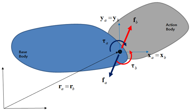
The vectors of the force and torque are defined from the reference marker  and the magnitude of each force is defined by a Function
Expression or User Subroutine. If the reference
marker is not defined, the reference marker will be taken as the inertia reference
frame. The position and orientation of the base marker are updated to same position
and orientation of the action marker in time domain as in the following
equations.
and the magnitude of each force is defined by a Function
Expression or User Subroutine. If the reference
marker is not defined, the reference marker will be taken as the inertia reference
frame. The position and orientation of the base marker are updated to same position
and orientation of the action marker in time domain as in the following
equations.
 | (4–56) |
 | (4–57) |
The force and torque defined by a Function Expressionor Vector Force User Subroutine can be a function of displacement, velocity, and acceleration of a marker on the rigid body, and other forces and variables as in the following equation:
 | (4–58) |
where  ,
,  and
and  are force functions and
  ,
,  and
and  are torque functions in x, y and z directions of the reference
frame.
are torque functions in x, y and z directions of the reference
frame.
The reacting force and torque on the base marker can be calculated as follows.
 | (4–59) |
If the base marker of the Vector is used to calculate a force, torque, or motion in a Function Expression or User Subroutine, the Motion solver can be unstable. This is because the position and orientation are not constant, but dependent on the position and orientation of the action marker.
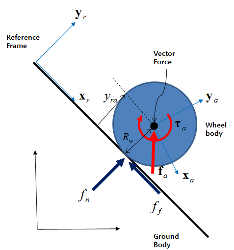
As shown in the figure above, the contact force of a rolling wheel on a slope can be modeled simply as a Vector. The reference frame is defined at a position on the slope and the x-axis and y-axis of the maker must be the tangent and normal directions of the slope as shown in the figure. A vector force is defined at the center position of the wheel. In this case, the action body is the wheel and the base body is the ground.
The contact condition can be represented by the following equation:
 | (4–60) |
where  is the distance of the center position of the wheel from the slope
and
is the distance of the center position of the wheel from the slope
and  is the radius of the wheel.
The contact normal force can be defined as the y-component of the force as in the following equation:
 | (4–61) |
where  and
and  are the contact stiffness and damping coefficients.
DY and VY are the displacement and
relative velocity functions. The arguments #1 and
#2 are the argument IDs for the action and reference markers.
For more information about this usage, refer to Function Expression Operation in the Motion Preprocessor User Guide.
are the contact stiffness and damping coefficients.
DY and VY are the displacement and
relative velocity functions. The arguments #1 and
#2 are the argument IDs for the action and reference markers.
For more information about this usage, refer to Function Expression Operation in the Motion Preprocessor User Guide.
The Coulomb friction force can be defined as the x-component of the force as in the following equation:
 | (4–62) |
where  is the dynamic friction coefficients. VX and
WZ are the relative velocity and angular velocity
functions.
is the dynamic friction coefficients. VX and
WZ are the relative velocity and angular velocity
functions.
The generalized torque due to the friction force can be defined as the z-component of the torque as in the following equation.
 | (4–63) |
Thus, from Equation 4–61, Equation 4–62, and Equation 4–63, the vector force can be defined as follows.
 | (4–64) |
A Vector is a very useful force entity. If contact between simple geometries is modeled using this force, the solving speed can be faster than using Rigid to Rigid 3D Contact (RTR3D Contact)