


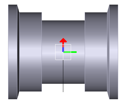
Figure 12.25: Profile tab in the Single Flange Roller property dialog
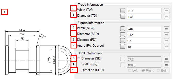
| Parameter | Symbol | Description | Dimension (Range) |
| 1. Dimension | N/A | This is figure to help understanding what to mean parameter. | N/A |
| 2. Width | TW | Use to set the width of tread. |
Length (Real>0.0) |
| 3. Diameter | TD | Use to set the diameter of tread. The half of diameter of tread is used assemble radius of Path |
Length (Real>0.0) |
| 4. Width | SFW | Use to set the width of flange. |
Length (Real>0.0) |
| 5. Diameter | SFD | Use to set the diameter of flange |
Length (Real>0.0) |
| 6. Distance | FD | Use to set the distance of flange |
Length (Real≥0.0) |
| 7. Angle | FA | Use to set the angle of flange |
Angle (Real≥0.0) |
| 8. Diameter | SD | Use to set the diameter of shaft. |
Length (Real>0.0) |
| 9. Width | SW | Use to set the width of shaft |
Length (Real>0.0) |
| 10. Direction | SDR | Use to set location of shaft. When "Left" is selected, shaft is created to left hand side When "Right" is selected, shaft is created to right hand side. When "Both" is selected, shaft is created to both side. | N/A |