12.15.4. FE Film Annotation

Geometry dimension

This is the geometry dimension information for the thin plate.

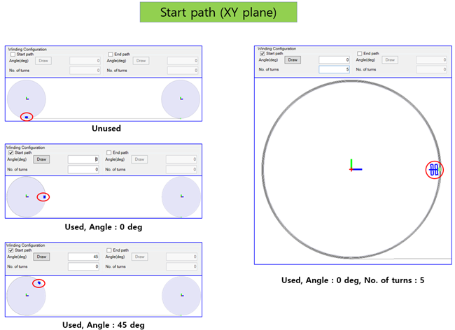
Winding configuration (Start path)

You can set the starting position and no. of turns using this function.

Figure 12.238: Winding configuration (start path)

Winding configuration (start path)

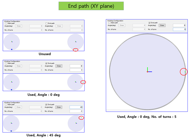
Winding configuration (End path)

You can set the end position and no. of turns using this function.

Figure 12.239: Winding configuration (end path)

Winding configuration (end path)

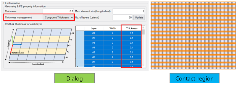
Various types of contact region

You can create various types of contact region using the following options:

  • One contact region

    Thickness management is set to Congruent Thickness, using the same thickness for each layer (see below).
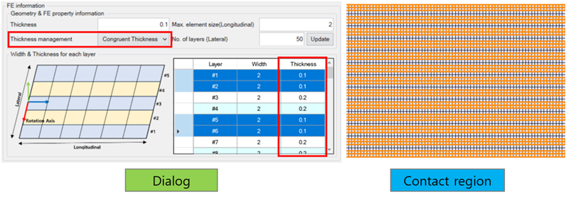
    Figure 12.240: One contact region

    One contact region


  • Two contact regions

    Thickness management is set to Congruent Thickness, using two different thicknesses for the layers (see below).

    Figure 12.241: Two contact regions

    Two contact regions


  • Contact region per layer

    Thickness management is set to Each Layer, in which case it does not matter if the thickness is the same or different for each layer (see below).
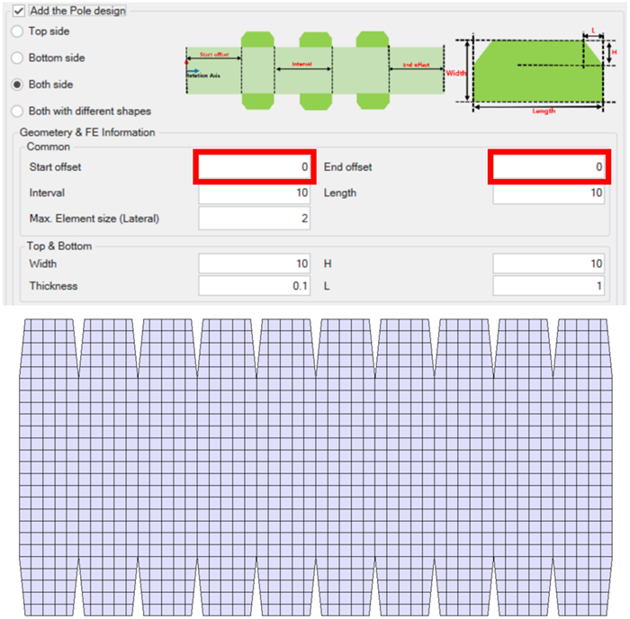
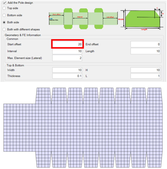
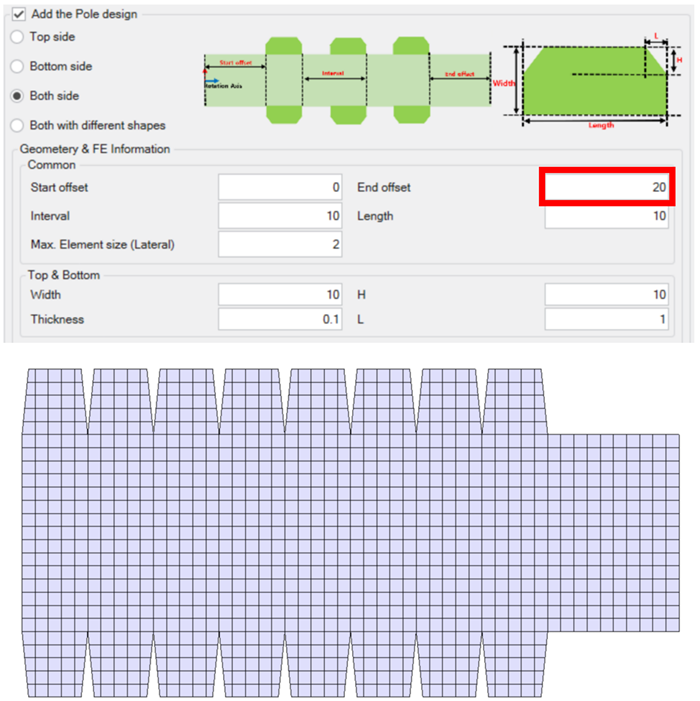
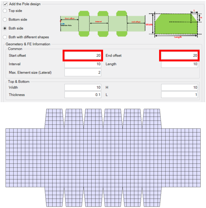
    Figure 12.242: Contact regions per layer

    Contact regions per layer


Pole location

You can determine the location of the pole using three options:
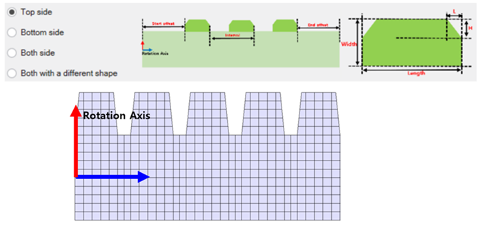
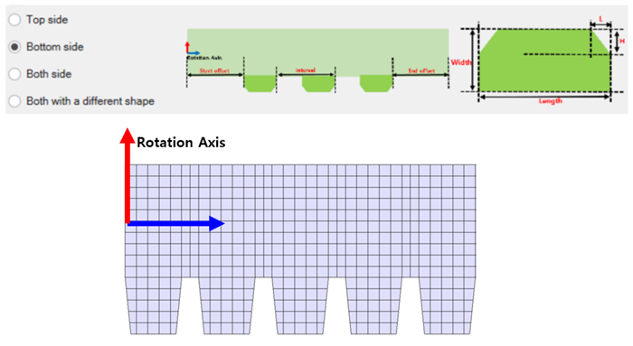
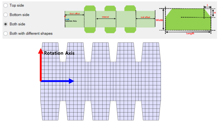
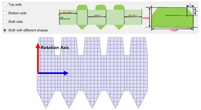
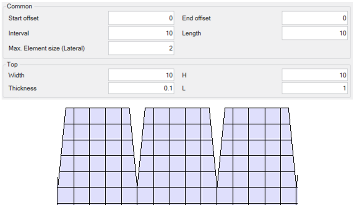
Figure 12.243: Pole location: Top side

Pole location: Top side


Figure 12.244: Pole location: Bottom side

Pole location: Bottom side


Figure 12.245: Pole location: Both sides

Pole location: Both sides


Figure 12.246: Pole location: Both with different shapes

Pole location: Both with different shapes


Various Pole shapes

You can create four types of pole shape by adjusting the following variables:
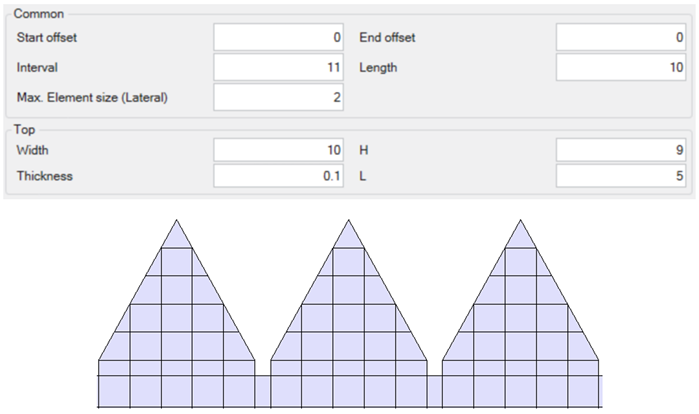
  • Triangle

    Condition: Width == H && L == 0.5 * Length

    Figure 12.247: Pole shape: Triangle

    Pole shape: Triangle


  • Quadrangle

    Condition: Width == H && 0< L < 0.5 * Length
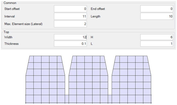
    Figure 12.248: Pole shape: Quadrangle

    Pole shape: Quadrangle


  • Pentagon

    Condition: 0< H < Width && L == 0.5 * Length

    Figure 12.249: Pole shape: Pentagon

    Pole shape: Pentagon


  • Hexagon

    Condition: 0< H < Width && 0< L < 0.5 * Length

    Figure 12.250: Pole shape: Hexagon

    Pole shape: Hexagon


Pole-free sections

This feature allows you to set pole-free sections at both ends of the film body.

Figure 12.251: Pole-free sections: None

Pole-free sections: None


Figure 12.252: Pole-free sections: Start offset

Pole-free sections: Start offset


Figure 12.253: Pole-free sections: End offset

Pole-free sections: End offset


Figure 12.254: Pole-free sections: Both

Pole-free sections: Both