


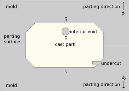
The Manufacturing Constraint Pull Out Direction enables you to deliver a design that is compatible with the casting process by preventing the formation of undercuts and internal holes. This capability only requires that you specify the direction in which to remove the mold, as illustrated below, for a cast part enclosed by two molds that are removed in opposite directions [13].
This constraint also provides the following Pull Out Options:
: This option aims to simplify the casting process. It ensures that the shape does not perforate along the specified direction and enables it to shrink perpendicular to the pull-out direction.
: You use this option to create a design that is compatible with a stamping or forging process. This option makes sure the shape does not perforate along the specified pull-out direction.
Go to a section topic:
Supported Methods
The Pull Out Direction constraint is available for the Mixable Density, Level Set, and Density Based optimization methods. These methods employ a built-in approach, namely that a dedicated machinery has been devised. Only the Level Set method provides the Pull Out Options properties.
Setup and Technical Details
The basic setup requires you to specify the Axis and the Direction properties along which the Pull Out Direction constraint is enforced. For the Level Set Based method, additional options are available, as described below.
| Method | ||
|---|---|---|
| Property | Mixable Density/Density Based Description | Level Set Based Description |
|
Axis |
The Axis property enables you to specify the axis of the Coordinate System along which the constraint is enforced. | |
|
Direction |
The Direction property enables you to specify whether the shape boundary is visible in one (one-sided) or two opposite (two-sided) directions. Note: For the Density Based method, when you specify the constraint using the Both Directions option, the application automatically imposes a parting surface. This surface passes from the origin of the Coordinate System and is perpendicular to the axis you specify in the Axis property. | |
|
Stamping |
NA |
Imposes no perforation in the working domain along the specified pull-out direction. |
|
No-Hole |
NA |
Imposes no perforation in the design along the specified pull-out direction. However, the shape is allowed to shrink perpendicular to the pull-out direction. Note: The
No-Hole property imposes a thick layer of
|
|
Exclusion Region |
You can decide whether to Include or Exclude Exclusions from the Analysis Settings. |
Exclusion regions are inherently considered as a formulation and automatically reshaped to comply with the pull-out direction (see images below). |

Here is an example of the extension of the Exclusion Region in a Level Set Based Optimization using the Pull Out Direction constraint.
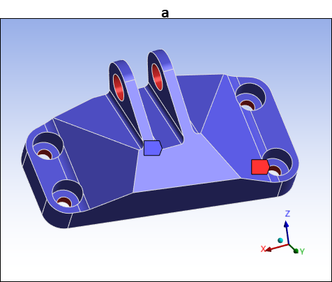
Exclusion Surfaces (a)
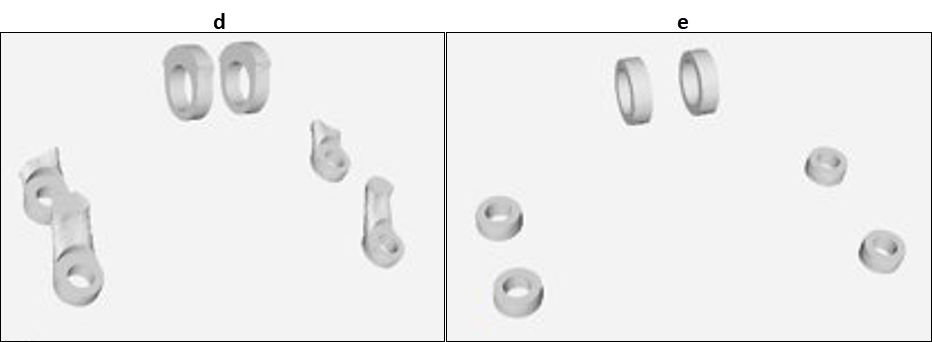
Exclusion Region (b) without Pull Out constraint. Extended Exclusion Region for (c) one-sided pull out in the +Z direction.
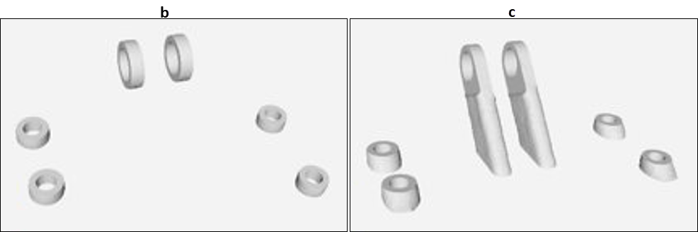
One-sided pull out (d) in the -Z direction and (e) two-sided pull out along the Z-axis.
Recommendations and Observations
As with any constraint, the Pull Out Direction shrinks the feasible domain and leads to smaller objective gain. With the No-Hole constraint, tiny perforations may still appear in the optimized shape (see the illustrations section).
Examples
Pull Out Example
This analysis examines the effect of the Pull Out Direction Manufacturing Constraint on a cantilever model with a spiral shape. The optimization problem is to minimize the structural compliance under a volume fraction constraint of 0.4.
- Set Up and Mesh
The environmental conditions and mesh are illustrated here.
- No Manufacturing Constraints
This result shows the optimized shape with no manufacturing constraints. The shape presents some cavities and undercuts along the Y-direction (indicated with red arrows). For this result, the structural compliance equals 5.22538e-02.
- Pull Out Direction in Both Directions
Here is the optimized shape with the Axis property set to and the Direction property set to . Using a two-sided Pull Out Direction constraint along the Y axis results, the previous cavities and undercuts have disappeared. The value of the structural compliance increased slightly to 5.27043e-02 (+0,9%).
- One-Sided Pull Out Direction
As illustrated below, changing the optimized shape by setting the Axis property set to and the Direction property set to , the shape changes dramatically because the side oriented in the -Y direction is considered as a parting surface. Disposing less freedom to evolve than in the two-sided, the value of the structural compliance increases more than previously, to 5.85545e-02 (+12.1%).
- Pull Out Direction and Member Size Constraints
The above formulation includes some thick regions that may present a problem to manufacture. Here you add a Member Size constraint specified with the Maximum property set to and the Max Size property set to
4mm(dmax = 4.0e-03). Adding the constraint helps to redistribute the available material, while respecting the Pull Out Direction constraint. The Max Size property specification (dmax = 4.0e-03) substitutes thick regions with thin nerves. By chance, this solution is better than the initial nominal optimization.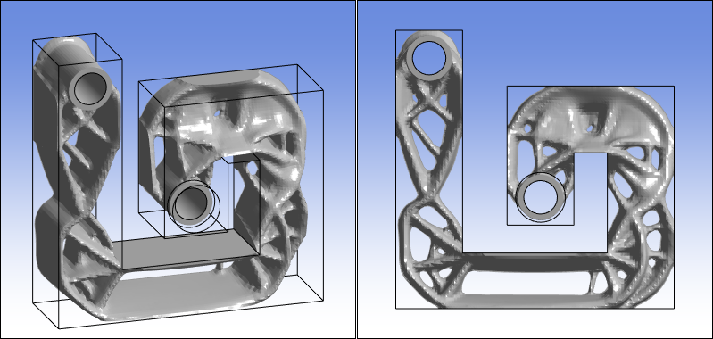
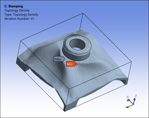
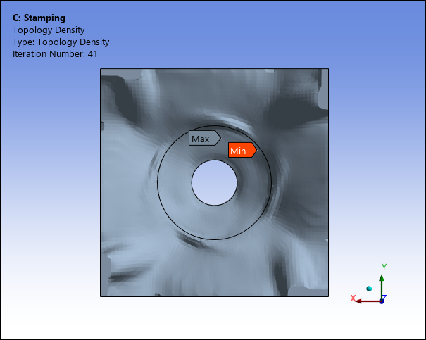
Stamping Example
Using the Level Set Based optimization method, this analysis examines the effect of the Pull Out Direction Manufacturing Constraint on an engine bracket part. The optimization problem is to minimize the structural compliance under a volume fraction constraint of 0.2.
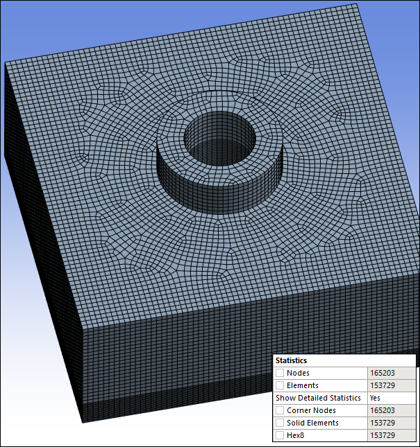
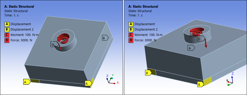
- Set Up and Mesh
The mesh and environmental conditions are illustrated here. The finite element model contains 153,729 elements.
Displacements (A and B) are scoped to two faces at the left hand corner of the base. A Moment and Force (C and D) are specified on the inner surface of the bracket.
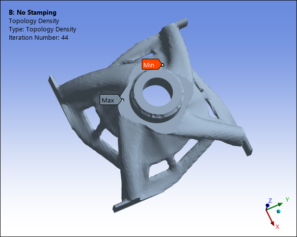
- No Manufacturing Constraints
The optimized result without considering manufacturing constraints is illustrated below. The structural compliance equals 0.0159048.
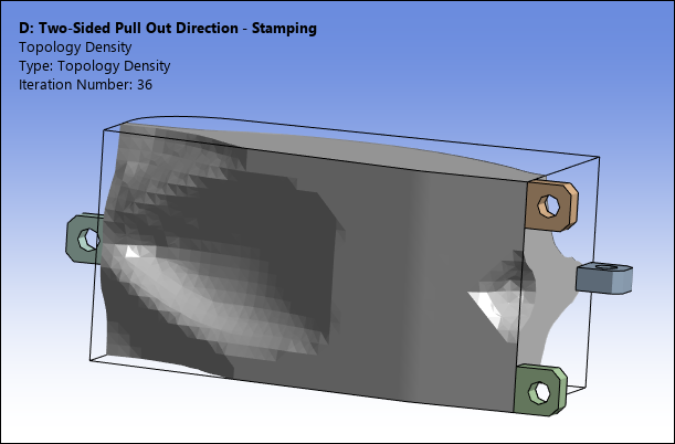
- Pull Out Constraint
Here, the Pull Out Option property is set to and specified in the Z-direction. This produces an optimized shape where no perforation appears in the Z-direction. The value of the structural compliance increases to 0.0176963 (+11.3%).
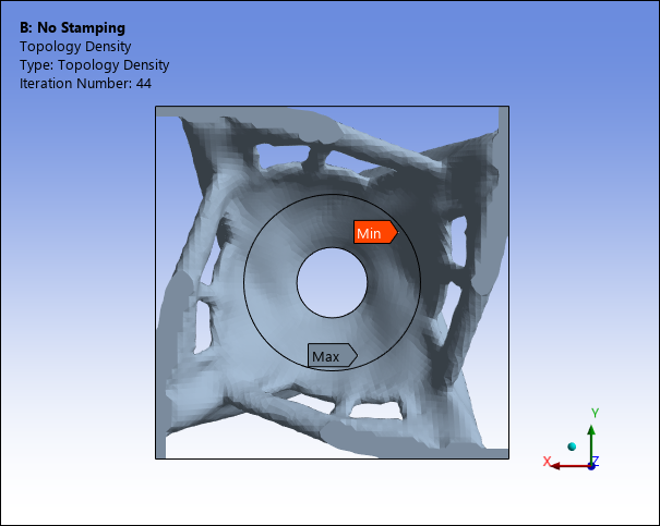
No Hole Example
Using the Level Set Based optimization method, this analysis examines the effect of the Pull Out Direction Manufacturing Constraint on a suspending arm. The optimization problem is to minimize the structural compliance under a volume fraction constraint of 0.4 and a two-sided Pull Out Direction constraint in the Y-axis.
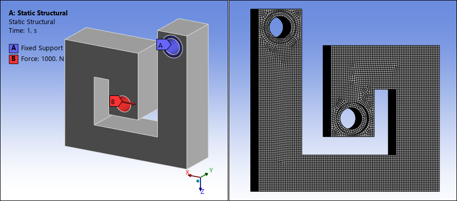
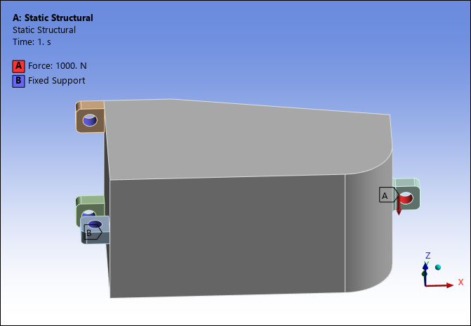
- Set Up and Mesh
The mesh and environmental conditions are illustrated here. The finite element model contains 14,714 elements.
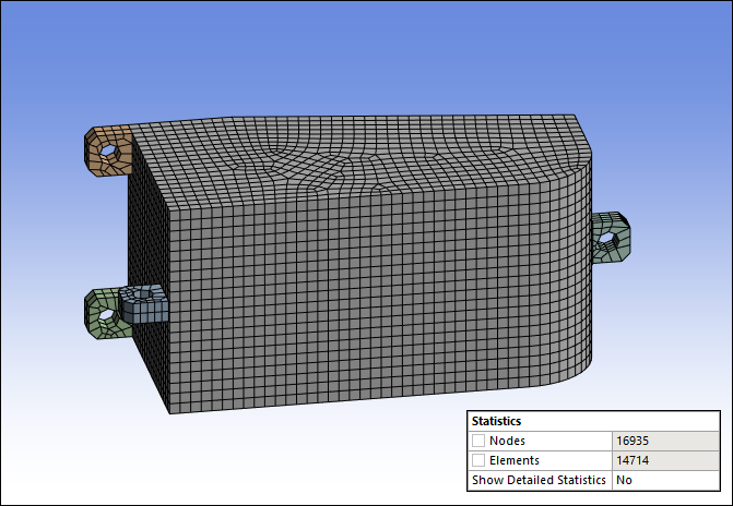
A Fixed Support (B) is scoped to the inner surface of the three parts on the right side of the model and a vertical Force (A) is applied to the inner surface of the part on the right side.
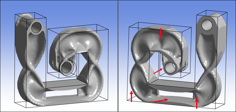
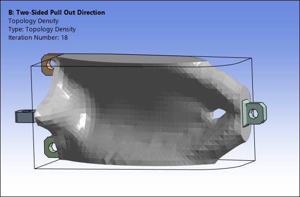
- Pull Out Constraint
For this result, the Pull Out Option property is set to . The optimized shape for the constraint pulled out in both directions (Direction property set to ) along the Y-axis (Axis property set to ). The structural compliance equals 1.34666e-03.
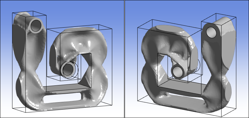
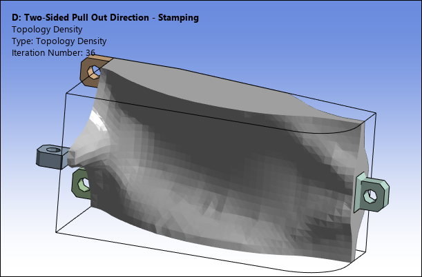
- Pull Out Constraint Stamping
For this result, the Pull Out Option property is set to . The optimized shape for the constraint pulled out in both directions (Direction property set to ) along the Y-axis (Axis property set to ). There are now no perforations along the Y-axis. The structural compliance increases to 1.3527e-03 (+0.45%).
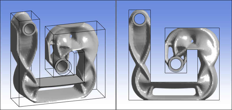
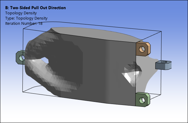
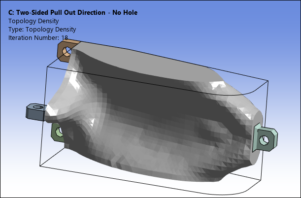
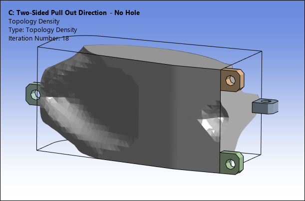
- Pull Out Constraint No Hole
For this result, the Pull Out Option property is set to . The optimized shape for the constraint pulled out in both directions (Direction property set to ) along the Y-axis (Axis property set to ). Compared to the default option, the small hole close to the loading disappears. More freedom to shrink perpendicular to the Y-axis is provided compared to the option. The structural compliance is similar to the result shown above (+0.1%).
References
[13] G. Allaire, F. Jouve, G. Michailidis, Molding direction constraints in structural optimization via a level-set method, Variational Analysis and Aerospace Engineering: Mathematical Challenges for the Aerospace of the Future, 2016.