Click > > .
Select S 5 only from the list.
Click > > .
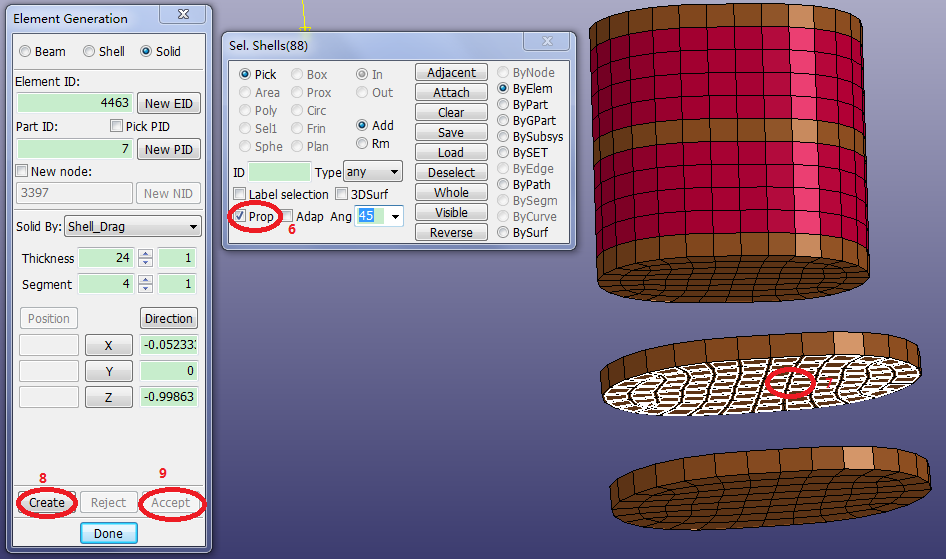
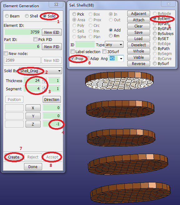
Select Solid.
Select Solid By: Shell_Drag.
Set Thickness=
24.Set Segment=
4.Click two times to set the drag direction direction to
0,0,-1.Select ByElem in the lower panel (gen select panel).
Activate Prop in the lower panel.
Click the lower face of the upper disc in the graphics window.
Click .
Click .
Repeat the previous step to fill in the gap between the top two discs.
Click .
Click in the Element Generation Interface to launch the Create Direction Dialog.
Select 2Nodes in the Create Direction Dialog.
Click node ID 223 in the graphics window.
Click node ID 94 in the graphics window.
Click in the Create Direction Dialog.

Click the lower face of the second disc from the bottom.
Click in the Element Generation Interface.
Click .