Files required:
1_3_Geom_Trim_model.zip: Download
After loading a model from an iges file, by default, the application will perform two preprocessing steps. First, it cleans up errors in the raw shapes from the iges file. After cleaning up, it will stitch the whole model into a shell. There are two stitching modes: manifold stitching and non-manifold stitching. The default stitching is manifold stichting.
This tutorial uses the iges file head_ansys.igs. In the pulldown menu, go to File > Open > IGES File and choose head_ansys.iges.
There are a lot of free edges (rendered as green color by default) in this raw model. Some free edges form the boundary of the model, but other free edges on the parent faces should be stitched together. You will also find four large round faces that should be broken into several sub-faces for stitching.
To break the four basic round face into several sub-faces:
Open the Geom Tools > Trim dialog.
Choose Mutual as the , then area select all faces in the view region
Click Apply to trim selected faces mutually. This will take a litter while.
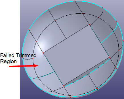
After mutual trimming, go to Geom Tools > Blank Entity.
In the Blank > Entity dialog, hide all knife shaped plannar faces. There is only one region that can't be trimmed well.
Click Unblank All to show all the faces back.
To trim the left region, use the trim tool to trim it manually:
Go to Geom Tools > Trim.
Choose Standard as the .
Select the knife shaped plannar face in that region into the Trim Tool list.
Select the failed trimmed face into the Be Trimmed Entities list.
Check Raw Trim Tool to recover the knife trim tool to a rectangle face.
Click Apply.
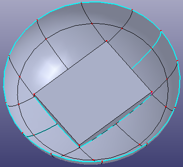
Go back to Geom Tools > Blank Entity to view the trimming results. The model has been trimmed well.
This is a non-manifold model. However, the default stitching model in IGES loading is manifold. To stitch them correctly:
Go to Geom Tools > Stitch.
Check All faces, then check Non-manifold Mode.
Click Apply.
Note: The All faces option selects all visible faces. If Group by part is checked, any two faces in different GParts will not be stitched together.
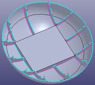
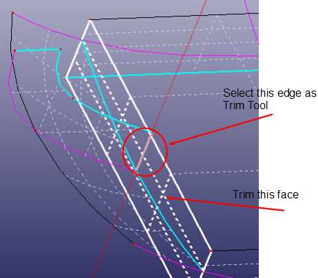
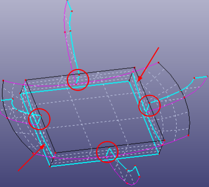
After step 5, there are still some problems in the model. In the figure below, the six regions which should be stitched into the model are labeled. Now, you should use these six edges as THE Trim Tool to trim the relative four plane faces.
Go back to the Trim dialog and choose Standard as the .
Select one edge as the Trim Tool to trim the relative plannar face (see the figure below).
Check Raw Trim Tool.
Click Apply.
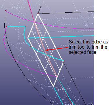
Select another edge as the Trim Tool to trim the relative plannar face (see the figure below).
Check Raw Trim Tool.
Click Apply.
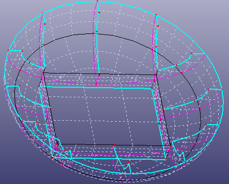
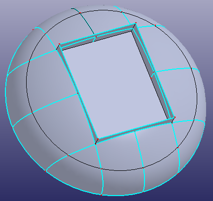
Perform similar trimming operations with all six regions. The final model is shown below.