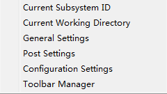
- Current Subsystem ID
Set current subsystem ID.
- Current Working Directory
Set current working directory.
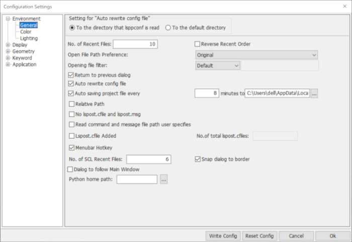
- Configuration Settings
Launch Configuration Settings interface.
- General Settings
Launch the General Settings interface.
- Post Settings
Launch the interface for Post-processing settings
- Toolbar Manager
Customize toolbars.
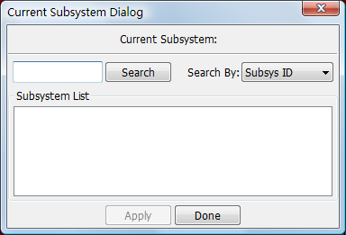
- Search
Search subsystem from subsystem list.
- Search By
Search subsystem by name or ID.
- Subsystem List
Click item to select.
- Done
Set current subsystem.
- Apply
Apply changes.
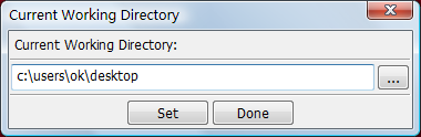
- Current Working Directory
Select a directory from the system.
- Set
Set the working directory.
- Cancel
Cancel operation.
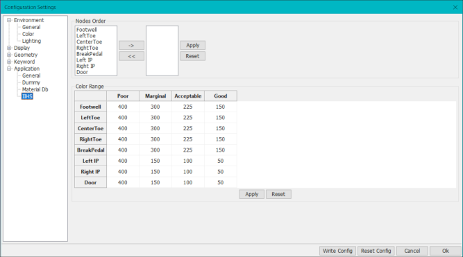
This Configuration Settings interface provides a convenience for modifying and previewing parameters in the preference file (.lsppconf).
The .lsppconf file is located in user's AppData directory for Windows and home directory for Linux individually, which stores information regarding the LS-PrePost configuration and is automatically saved every time LS-PrePost exits.
Tip: When updating to a new version of LS-PrePost, you don't have to delete your old .lsppconf file to get the new features because the software will refresh it automatically.
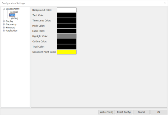
- Background Color
Click to set background color.
- Text Color
Click to set text color.
- Timestamp Color
Click to set timestamp color.
- Mesh Color
Click to set mesh line color.
- Label Color
Click to set label color.
- Highlight Color
Click to set highlight color.
- Outline Color
Click to set outline color.
- Triad Color
Click to set triad color.
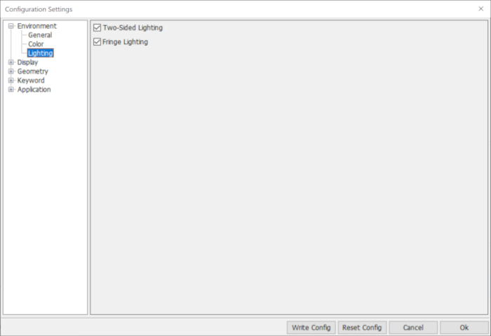
- Two-Sided Lightingr
Set twoside lighting.
- Fringe Lighting
Set fringe lighting.
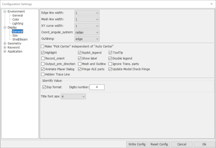
- Edge line width
Select edge line width.
- Mesh line width
Select mesh line width.
- XY curve width
Select XY curve line width.
- Coord_angle_system
Select coordinate system in radian or degree.
- Outlining
Set draw model outline mode.
- Highlight
Highlight selected entities.
- Xyplot_legend
Set xyplot legend.
- ToolTip
Show/no tooltip.
- Record_orient
Record to lspost.cfile with orientaton (quat/zoom/pan).
- Show label
Show node label on/off only for trace dialog.
- Double legend
Show both fringe and vector color bars at the same time.
- Output_prin_directionl
Output principal strain/stress direction to lspost.msg while fringing vector plot.
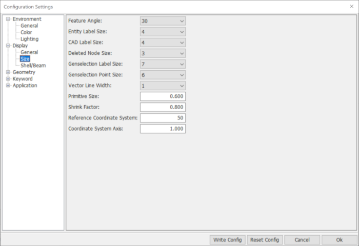
- Feature angle
Select feature angle value.
- Entitylabel size
Input entity label size.
- Cadlabel size
Input cad label size.
- Primitive size
Input primitive size.
- Shrink factor
Input shrink factor.
- Polygon offset factor
Input polygon offset factor.
- Polygon offset unit
Input polygon offset unit.
- Reference Coordinate System
Input Reference Coordinate System size.
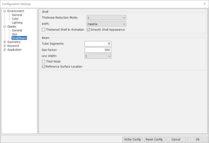
- Thickness reduction mode
Select shell thickness reduction mode.
- Shell ipt
Select the shell Integration point location for fringing.
- Beam tubesegs
Change the number of segments to use when drawing a beam as a tube.
- Beam sizefactor
Input beam size factor.
- Beam_line_width
Draw beam line width.
- Beam 3rd node
Draw beam third node.
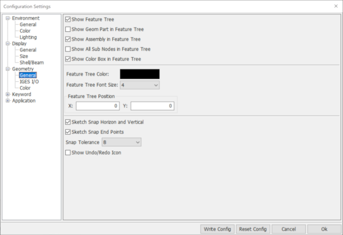
- Show feature tree
Show or hide feature tree.
- Show feature tree geom_part
Show or hide feature tree geometry part.
- Show feature tree assembly
Show or hide feature tree assembly.
- Show feature tree all nodes
Show or hide feature tree all nodes.
- Show Color Box in Feature Tree
Show or the hide color boxes in the feature tree.
- Feature tree color
Click to set feature tree color.
- Feature tree font_size
Click to set feature tree font size.
- Feature Tree Position X
X-position of feature tree.
- Feature Tree Position Y
Y-position of feature tree.
- Sketch Snap Horizon and Vertical
Turn horizonal and vertical point snapping on and off in sketch.
- Sketch Snap End Points
Turn end point snapping on and off in sketch.
- Snap tolerance
Select snap tolerance.
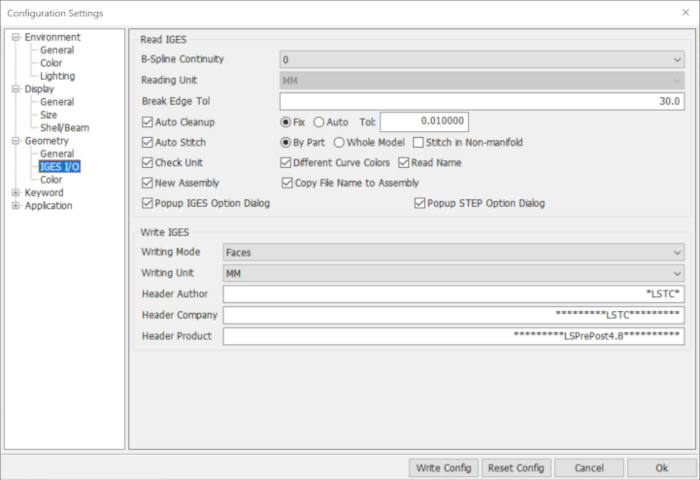
- Bspline continuity
Select reading iges bspline continuity(0,1,2).
- Reading unit
Select reading iges unit.
- Break edge tol
Input breaking edge tolerance.
- Auto cleanup
whether need to clean up shapes.
- Fix
Using fix tolerance to cleanup shapes.
- Auto
Using auto tolerance to cleanup shapes.
- Tol
Input auto cleanup tolerance.
- Auto Stitch
Whether need to stitch faces within a part or stitch faces for the entire model (connecting parts together), and whether or not to stitch in non-manifold.
- Check unit
Automatically detect iges file unit.
- New Assembly
Read the shape into a new assembly
- Copy File Name to Assembly
Copy current IGES file name into the new assembly
- Popup IGES Option Dialog
Popup option dialog when reading an IGES file.
- Popup Step Option Dialog
Popup option dialog when reading a STEP file.
- Writing mode
Iges file writing mode "Faces" or "BRep".
- Writing unit
Select writing iges unit.
- Header author
Input writing file head author info.
- Header company
Input writing file head company info.
- Header product
Input writing file head product info.
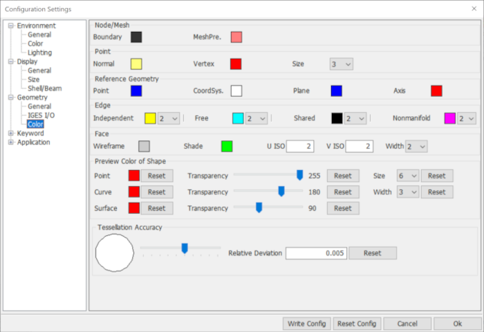
- U ISO
Input geometry shape face ISO U curves number.
- V ISO
Input geometry shape face ISO V curves number.
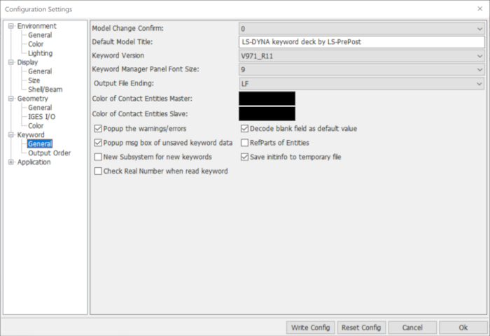
- Default Model Title
Default model title if no title (*TITLE) is loaded.
- Keyword Version
Select Keyword version.
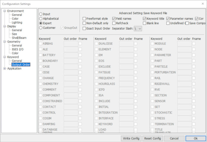
- Input
Output keyword order by input order.
- Alphabetical
Output keyword name in alphabetical order.
- Expert
Output by expert recommended sequence.
- Customer
Output keyword name in customer order.
- GroupOut
Output keyword as group ,such as *PART,*SECTION,etc.
- Freeformat style
Output data in Free Format/Fix Format.
- Field names
Output keyword field names.
- Keyword title
Output keyword *Title.
- Parameter names
Output parameter names instead of real data.
- Comments
Output keyword comments.
- Non Default only
Not output zero if only default value is zero.
- Refchk
Output data with all reference data.
- Blank line
Output blank if all line fields or all right side fields are 0 0r 0.0.
- Undefined Check
Output Undefined link in current output with 0.
- Save Component
Check to save component part.
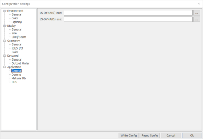
- LS-DYNA(S) exe
Define the file path for the LS-DYNA single precision executable.
- LS-DYNA(D) exe
Define the file path for the LS-DYNA double precision executable.
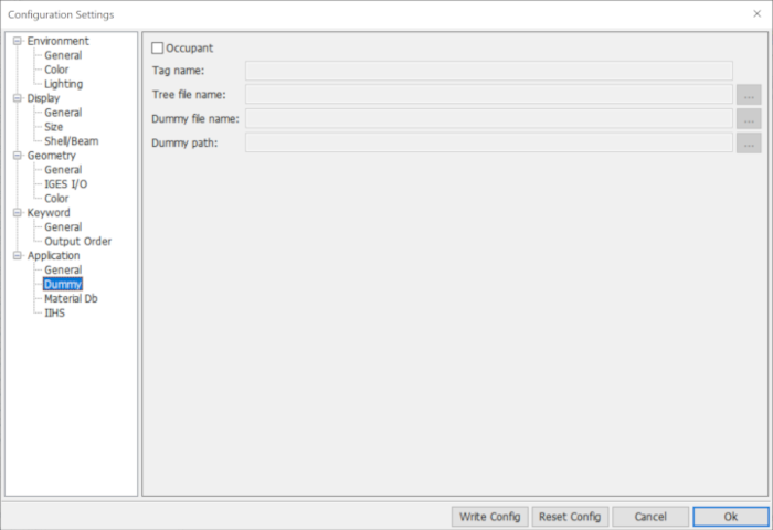
- Occupant
Click to enable/disable dummy info widgets.
- Tag name
Input tag name.
- Tree file name
Click to browse dummy tree file name.
- Dummy file name
Click to browse dummy file name.
- Dummy path
Click to browse dummy path.
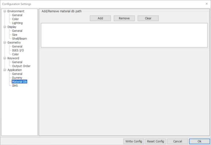
- Add
Click to browes default material datebase path.
- Remove
Remove selected material datebase path from list.
- Clear
Clear the material datebase path list.
This interface provides a convenience for reorganizing the icons of the right toolbar, and moving the icons in the second level toolbar to bottom toolbar, favorite1, favorite2.
It will automatically create a perference file(Configure_Toolbar.cfg) every time lspp exits, which records all the information regarding LS-PrePost right and bottom toolbar icons, and is located in user's AppDate directory for Windows and home directory for Linux individually.
Tip
When updating to a new version of LS-PrePost, you don't have to delete your old Configure_Toolbar.cfg file to get the new features because the spftware will refresh it automatically.
- Sample
A sample to show how to customize toolbars.
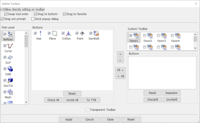
- Allow directly editting on toolbar
Allow directly dragging the icon to bottom toolbar, favor1 and favor2.
- Drag out prompt
Give prompt or not when dragging icon.
- Dock popup dialog
Dock popuped dialog or not.
A sample to show how to add commonly used function to Favor1 using Define toolbar interface.
- Step 1:
Go to the menu Settings->Toolbar Manager dialog.
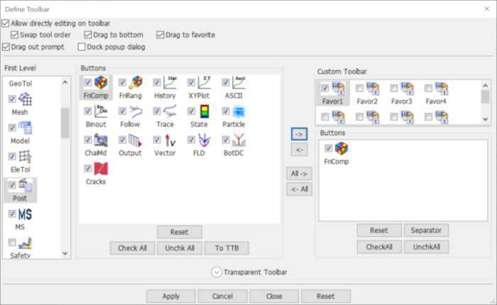
- Step 2:
Click the icon Post and FriComp from Fist level and Buttons list individually, then click icon "->", see Figure 1.
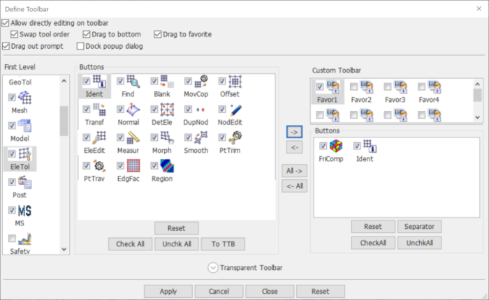
- Step 3:(continue to add more icon to Favor1)
Click the icon EleTol and Ident from Fist level and Buttons list individually, then click icon "->";, see Figure 2.
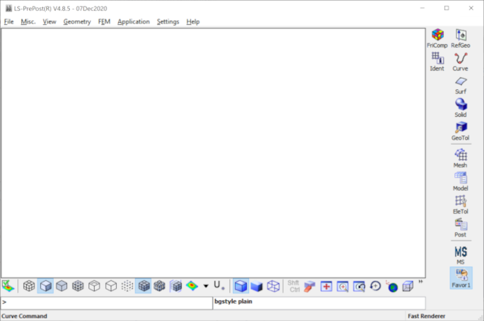
- Step 4:
Click Apply to take effect, Close the Define toolbat interface, then click icon Favor1 on the right toolbar, you will see that ident and FriComp are added to Favor1 , see Figure 3.