


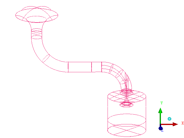
In this tutorial example, you will generate and smooth a tetrahedral mesh for a piston/valve configuration. The complete geometry is shown in Figure 170: Piston Valve Geometry.
In the process, you will use features of Ansys ICEM CFD designed to improve your efficacy when working with certain types of geometries. The first tool is Build Diagnostic Topology. This tool creates curves and points from surface edges and corners depending on their proximity. It will also remove curves or points when surfaces or curves meet below a specified shallow angle. Refer to , under > , in the Help documentation for more detail.
Also, you will be required to define a thin cut in the Geometry to mark a region where Ansys ICEM CFD Tetra will respect two surfaces that meet at a shallow angle. Refer to , under > , in the Ansys ICEM CFD User's Manual for more information. Similarly, Curvature/Proximity Based Refinement is used to resolve geometries with small radius of curvature or in close proximity to one another. Refer to , under > , in the Help documentation for more information on Curvature/Proximity Based Refinement.
This tutorial demonstrates how to do the following:
Prepare the geometry using Build Topology and defining parts.
Set the mesh parameters.
Generate a tetra mesh, and compute prism layers.
Check the mesh for errors.