


The Part list panel displays four types of objects:
model parts - parts defined by the dataset;
cases - an object that represents a particular dataset;
LPARTS - parts that are not necessarily loaded from a dataset but could be;
derived parts - parts that are created within EnSight.
The Part list panel supports both user-defined groups as well as data set defined groups (if the data format and reader supports groups). Figure 3.2: Part List shows a single dataset as indicated by Case 1. The dataset defines four groups: car, body, wheels, rail. All other objects are model parts except for the groups, Case 1, windows, windshields, and Clip_plane. Windows and windshields are LPARTs and are indicated as such by their gray text. Clip_plane is a derived part and is indicated as such by the P icon to the left of its parent parts: bumpers, floor, front body, hood, and rear_body. Clip_plane is also the selected part as indicated by its blue background. Parts tires and wheels are the current Feature Panel selected parts as indicated by the pencil icon to the left of their names.
Because the Part list panel supports grouping, objects within the list panel may be drag and dropped between groups. The context sensitive menu also has operations related to groups.
The Part list panel has a filter widget above the part list columns.
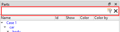
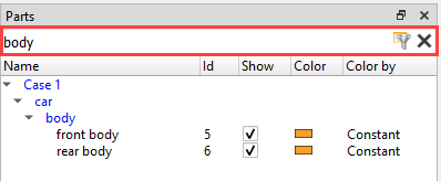
The list of parts can be filtered by typing into this widget and pressing the return key or clicking the "filter" icon. All parts with names not selected by the text will be hidden from the list. Figure 3.6: Part list filtered by text shows the list of parts filtered to those including the text "body" in its name.
The filter text can be cleared and the view of parts reset by clicking on the "X" icon to the right of the "filter" icon. While part selections work as expected while a list filter is applied, they will be reset when the filter string changes or is cleared.
The filter text can include "glob" style wildcard characters. The asterisk (*) can be used to match a sequence of characters of arbitrary text. The question mark (?) can be used to match any one arbitrary character. The syntax [a-z] will match a single character in the range from 'a' to 'z'. This can be used to effectively filter numbers, etc. Note that the filter string is considered to start and end with implicit "*" characters and in most cases simple substrings without glob wildcards can be used to filter the list effectively.
Figure 3.2: Part List also shows the default view for the Part list panel. By default the list panel has columns for Name, Id, Show, Color, and Color by as described in the next section. Name is the default sort column. Clicking on a different column header will change the sort.
The column header context sensitive menu has additional options for how LPARTS should be displayed and an option for whether part-based tooltips should be displayed (see Figure 3.3: Parts). LPARTS can be set to always be shown, never shown, or only shown if the associated part is not loaded; this is the default. Part-based tooltips are shown when the mouse is held stationary over a part name. They indicate if the part is a model part or if it's a derived part; and, if it is a derived part, what its parent parts are.
Selecting the Customize... option from the column header context sensitive menu displays a dialog for choosing which part attributes to display and in what order. Table 3.1: Attributes lists the available attributes.
Table 3.1: Attributes
|
Bounding Rep |
How the elements should be drawn while the scene is being actively moved. |
|
Color |
The part color when not colored by a variable. |
|
Color by |
Whether the part is colored by a variable or a constant color. |
|
Description |
The name of the part. |
|
Displace by |
The name of the optional variable used to apply node displacements. |
|
Element labels |
Whether element labels are displayed for the part. |
|
Hidden line |
Whether hidden line rendering applies to the part. |
|
Hidden surface |
Whether hidden surface rendering applies to the part. |
|
Id |
The part id number. |
|
Line width |
The element line thickness (1-4). |
|
Node labels |
Whether node labels are displayed for the part. |
|
Reference frame |
The coordinate frame number the part belongs. |
|
Representation |
How elements are drawn for the part. |
|
Scale factor |
The scaling factor applied to elements. |
|
Show |
The part visibility status. |
|
Total time limit |
Total emission time for particle trace parts. |
|
Type |
The part type (for example, model, clip, particle trace). |
|
Value |
The special value for certain part types (for example, isosurface value). |
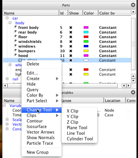
The context sensitive menu for the Part list panel varies depending on what the mouse is over in the Part list panel when the mouse is right-clicked. Figure 3.7: Part Context Menu shows the menu when the context menu is displayed while over a part. The menu shows an appropriate subset of options if the mouse is over the background, the Case name, or a group name. Table 3.2: Available Menu Options describes the various menu options that may be available.
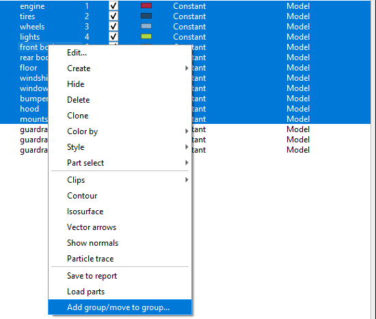
Table 3.2: Available Menu Options
|
Edit... |
Displays the Feature Panel with the current selection marked for editing. Items marked for editing by the Feature Panel will have a pencil icon displayed to the left of their name. |
|
Create |
The submenu lists the derived parts that may be created using the currently selected parts as parent parts. See Figure 3.8: Create. Choosing one of the derived part types will display the Feature Panel, if it is not already visible, and place it in create mode for the selected type. The currently selected part(s) will be used as the parent(s) for the newly created part. |
|
Hide / Show |
Toggles visibility off/on for the currently selected part(s). |
|
Delete |
Deletes the currently selected items. If the deleted part(s) are model parts, they will be deleted and the list will then show the associated LPART depending upon the setting of the Display loadable parts menu option previously described. |
| Clone |
Creates a independent copy of either a model or a created part including all of its attributes on both the client and the server. A cloned model part is a reloaded model part with its attributes updated to match the original. A cloned created part has the same parent as the original with all the same attributes. |
|
Color by |
Parts can be colored by a constant color (for example, Red) or false (pseudo) colored by a variable. Select Variable will display the variable chooser dialog. Figure 3.9: Color By shows this submenu. Figure 3.10: Variable Chooser Dialog shows the variable chooser dialog whereas Figure 3.11: Color Dialog Picker shows the color picker dialog. Choosing the menu option Make Transparent will make the part 50% transparent. Adjust Transparency... will display the transparency adjustment slider dialog (see Figure 3.12: Transparency Adjustment Slider Dialog). |
| Style | Copy, paste, attributes of/to the object from another part. |
|
Part select |
Several menu options are available for setting the current part selection. See Figure 3.13: Part Select for the submenu and Table 3.4: Part Select Options for a description of the options. |
|
Change tool |
This menu item is only visible if the selected part is a clip part. Selecting one of the items changes the type of tool used to create the clip part. See Figure 3.17: Change Tool. |
|
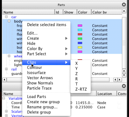
Clips |
Creates a clip part using the currently selected part(s) as the parent part(s). It differs from the Create menu option in that the Feature Panel is not displayed. See Figure 3.18: Clips. |
|
Contour |
Creates a contour part using the currently selected part(s) as the parent part(s). The Variable Chooser dialog is displayed to select the variable to use for the contour calculation. It differs from the Create menu option in that the Feature Panel is not displayed. |
|
Isosurface |
Creates an isosurface part using the currently selected part(s) as the parent part(s). The Variable Chooser dialog is displayed to select the variable to use for the isosurface calculation. The midpoint value of the selected variable is the value used for the isosurface. This option differs from the Create menu option in that the Feature Panel is not displayed. |
|
Vector arrows |
Creates a vector arrow part using the currently selected part(s) as the parent part(s). The Variable Chooser dialog is displayed to select the variable to use for the vector arrows if there is more than one vector variable available. It differs from the Create menu option in that the Feature Panel is not displayed. |
|
Show normals |
Creates a vector arrow part where the arrows represent part element normals. |
|
Particle trace |
Creates a particle trace part using the currently selected part(s) as the parent part(s). The Variable Chooser dialog is displayed to select the variable to use for the part if there is more than one vector variable available. It differs from the Create menu option in that the Feature Panel is not displayed. |
| Save to report | Save as an ADR Report Object. See Use Reports. |
|
Add group/move to group... |
A dialog is displayed to either create a group with the selected parts.If a group already exists, the dialog will also allow you to select which group to re-assign the selected parts to. |
|
Create new group... |
Creates a new empty group. |
|
Rename group... |
A dialog is displayed to rename the currently selected group. |
|
Delete group |
Deletes the selected group. Contained parts are moved to the group's parent. |
|
Rename case... |
A dialog is displayed to rename the case name. |
|
Load part |
Depending on the selected LPART either the Unstructured or the Structured Part Loader dialog will display. These are described later. |
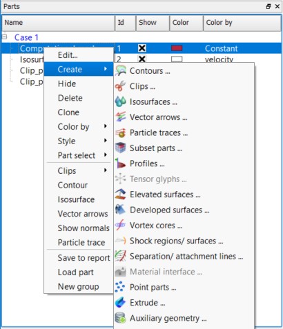
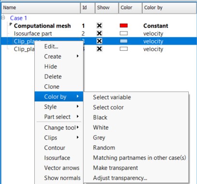
Table 3.3: Color By
| Select variable | Will pop up the variable chooser dialog. Figure 3.10: Variable Chooser Dialog |
| Select color | Select a color to color this part by. Figure 3.11: Color Dialog Picker |
| Black | Color the part black |
| White | Color the part white |
| Grey | Color the part grey |
| Random | Color the part by a color randomly selected |
| Matching part names in other cases |
If you have more than one case loaded, then this will color the selected parts the same color as the parts in the other case with a matching part name. |
| Make transparent | Make the part somewhat transparent |
| Adjust transparency | Bring up a slider bar to adjust the transparency. Figure 3.12: Transparency Adjustment Slider Dialog |
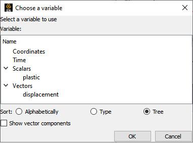
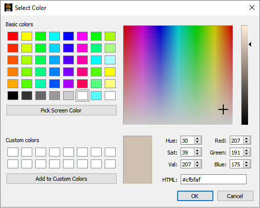
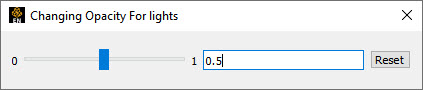
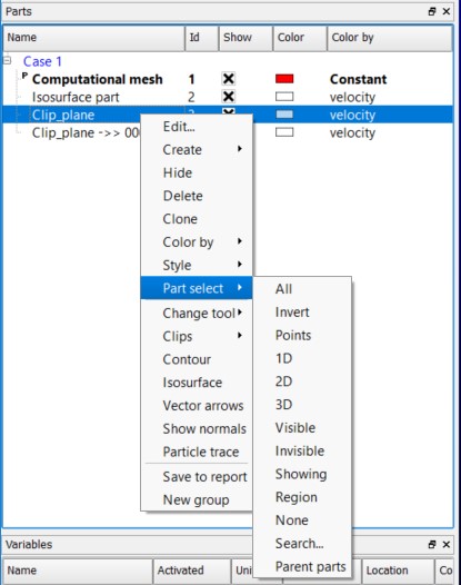
Table 3.4: Part Select Options
|
All |
Select all parts |
|
Invert |
Inverts the current part selection |
|
Points |
Selects only point parts |
|
1D |
Selects only parts with 1D elements |
|
2D |
Selects only parts with 2D elements |
|
3D |
Selects only parts with 3D elements |
|
Visible |
Select parts that are have their visibility attribute on |
|
Invisible |
Select parts that are have their visibility attribute off |
| Showing | Select part(s) that can be seen in the graphics window |
|
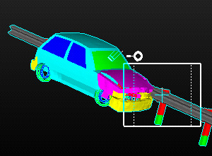
Region |
Selects parts underneath the region tool (see Figure 3.14: Region). If the region tool is not displayed in the graphics window, then this option will display it and indicate that it must be first visible via a message dialog. Once the region tool is displayed, this option will then select all the parts, overlapping or not, that are contained within the region tool. |
|
None |
Deselects all parts |
|
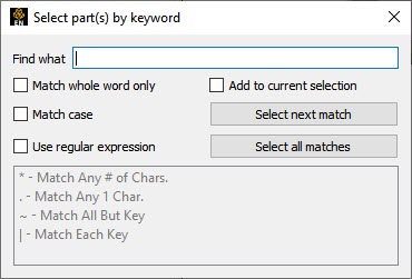
Search... |
Displays the Search Parts By Keyword dialog (see Figure 3.15: Search). Parts are selected that match the specification indicated in the dialog. |
|
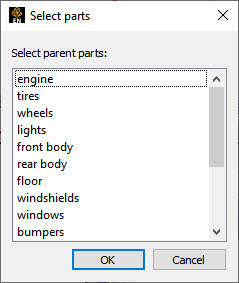
Parent Parts |
Selects the parent parts of the currently selected part(s). If no parts are selected, then a Select Parent Parts dialog is displayed (see Figure 3.16: Parent Parts). |
If the Load Parts option is selected over an unstructured LPART, the dialog shown in Figure 3.19: Unstructured LPART is displayed to load the associated part. Table 3.6: Structured LPART describes the fields in the dialog. If Load Parts option is selected over a structured LPART, the dialog shown in Figure 3.20: Structured LPART is displayed. Table 3.5: Unstructured LPART Options describes the fields for that dialog.
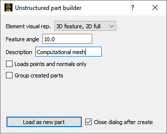
Table 3.5: Unstructured LPART Options
|
Element visual rep. |
The sets the element visual representation for the part. |
|
Feature angle |
The number of degrees for feature angle element representation. |
|
Description |
The name to use for the part once it is loaded. This value is initialized with the name found in the data set. If multiple parts are loaded simultaneously, this input is inactive and the loaded parts will use the names found in the data set. |
| Loads point and normals only | Don't load the part(s) as surfaces, rather show only the nodes and also load the normal at each node. |
|
Group created parts | Put these loaded part(s) in their own group. |
|
Close dialog after create |
If unchecked, the dialog stays open to allow loading of the same part multiple times. This may be useful if you wish to display the same part with different attributes. |
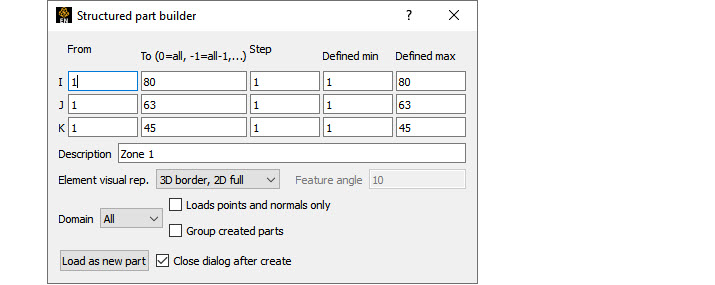
Table 3.6: Structured LPART
|
From (I,J,K) |
The starting values along the I,J,K axes. |
|
To (I,J,K) |
The ending values along the I,J,K axes. For convenience, zero may be specified to represent the maximal value. Negative values indicate values N less than the maximal values (for example, -2 means 2 less than the maximal value). Zero and negative values are useful when loading multiple structured parts simultaneously. |
|
Step (I,J,K) |
The I,J,K stride. Steps greater than 1 are useful for loading reduced resolutions of the part(s). |
|
Defined Min (I,J,K) |
The actual minimum values for the I,J,K axes as defined by the dataset. |
|
Defined Max (I,J,K) |
The actual maximum values for the I,J,K axes as defined by the dataset. |
|
Description |
The name to use for the part once it is loaded. This value is initialized with the name found in the data set. If multiple parts are loaded simultaneously, this input is inactive and the loaded parts will use the names found in the data set. |
|
Element visual rep. |
The sets the element visual representation for the part. |
|
Feature angle |
The number of degrees for feature angle element representation. |
|
Domain |
Ibanking domain to use, Inside (iblank value of 1), or outside (iblank value of 0) |
|
Close dialog after create |
If unchecked, the dialog stays open to allow loading of the same part multiple times. This may be useful if you wish to display the same part with different attributes. |
EnSight part groups include the ability to apply a collection of rigid body transforms to a group which, in turn, transforms the parts in that group. Additionally, transformations for nested groups are applied in a hierarchical fashion. This allows for a grouping in the part tree to apply local transformations in local reference frames. For example, a group might specify the rotation of a tire over its axle. While a higher level transform could specify motion relative to the body of the car itself.
These transforms occur on the EnSight client and are visual only. Therefore, for example, they are not included in calculations done on the server.
Applying grouping to the car crash example part list may result in a display as follows
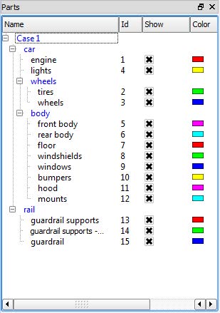
A group transformation on the wheels group will change the coordinates of parts 2-3 and a group transformation on the body group will change the coordinates of parts 5-12. A transformation applied to the car group will be applied to parts 2-3 after the wheels transformation and parts 5-12 after the body transformation as well as parts 1 and 4.
The group transformation can be modified using the transformation dialog that can be accessed by right-clicking the group and selecting the Edit group transform... option. If you right-click the car group and chooses Edit group transform... then the dialog will look as follows:
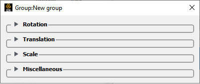
The dialog is always connected to the group that was right-clicked, and the dialog does not change the target group based on selection. This allows for multiple group dialogs to be open at the same time, each editing a different group. The title of the dialog shows the group the dialog is transforming. For example, notice above that the title of the dialog is Group: car.
There are three basic transformations: Rotation, Translation and Scale as well as some additional options in the Miscellaneous category. Each section can be opened by clicking the associated section turn down. Unlike EnSight frames, the individual transformations are maintained independently. This and the hierarchical nature of groups makes it a simpler to modify individual transformation.
Rotation Section
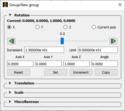
This section controls the rotation property of the group transformations. The current rotation is always displayed at the top of the section as the axis of rotation (the normal as nx, ny, nz) and the angle in degrees (default axis 0.0, 0.0, 1.0, and default angle 0.0 degrees). The buttons below that value can be used to select the specific axis that the slider below it controls X, Y, Z or Current axis. The Current axis option will rotate over the axis listed at the top of the section. The slider allows the user to interactively increment/decrement the angle over selected axis. The slider will temporarily modify the rotation and apply the result when the slider is released, at which point it will snap back to the center and the current rotation will be updated at the top. The buttons on the right and left will increment or decrement the angle by the value noted below. Dragging the slider all the way to the right or left will result in the axis value changing by the Limit amount (the default is -90, +90 degrees).
The rotation can be explicitly set by entering values into the Axis X, Axis Y, Axis Z and Angle fields and clicking Set or incremented by the fields by clicking . The button can be used to copy the current rotation values into the fields, which can be useful with to be an undo operation for example. Finally, the button will set the rotation values back to their default values of 0.0, 0.0, 1.0, 0.0.
By default, the rotation is applied about the global origin located at 0.0, 0.0, 0.0. If another origin is desired, use the Centroid offset option in the Miscellaneous section (discussed later, below).
For example, when you first open the dialog, you find the values Current: 0,0,1,0 This is the default value. It corresponds to a rotation around the axis (0,0,1) of an angle 0. Every time you apply a rotation, the value of Current is updated. It gives you the axis and angle of rotation that you should apply to the initial configuration of the group in order to get the position of the group elements you are seeing now. In other words, it gives you the composition of all the rotations that you have applied to the group. Now, if you apply first a rotation of angle=90 degrees around the axis (0,0,1) (that corresponds to axis Z) and then a rotation of angle = 90 degrees around the axis (0,1,0) (that corresponds to axis Y), the value of Current is (0.5774, 0.5774, -0.5774) and angle = 120.0. If you now do "reset", so that the group has no initial rotation, and make a rotation around axis (0.5774, 0.5774, -0.5774) of angle 120 by putting these values by hand, you see that the result you obtain is the same.
Translation Section
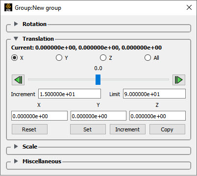
This section controls the translation property of the group transformations. The current translation in X, Y, Z is always displayed at the top of the section. The buttons below that value can be used to select the specific axis that the slider below it controls. The slider allows the user to interactively modify the selected axis. The slider will temporarily modify the translation and apply the result when the slider is released, at which point the slider will snap back to the center. The buttons on the right and left will increment or decrement the axis value by the Increment value noted below. Dragging the slider all the way to the right or left will result in the axis value changing by the Limit amount.
The translation can be explicitly set by entering values into the X, Y and Z fields and clicking or incremented by the X, Y and Z fields by clicking . The button can be used to copy the current translation values into the X, Y and Z fields, which can be useful with to be an undo operation for example. Finally, the button will set the translation to 0.0, 0.0, 0.0.
Scale Section
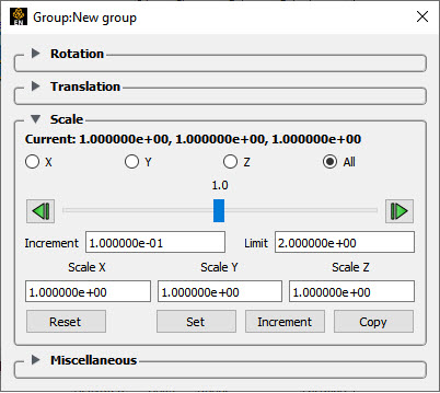
This section controls the scale property of the group transformations. The current scaling factor in X, Y, Z is always displayed at the top of the section. The buttons below that value can be used to select the specific axis that the slider below controls. Selecting All scales all geometry uniformly. Selecting X, Y or Z will result in anisotropic scaling of the geometry only in that axis direction.
The slider allows the user to interactively modify the scaling. The slider will temporarily modify the scale and apply the result when the slider is released, at which point it will snap back to the center. The buttons on the right and left will increment or decrement the axis value by the 'Increment' value noted below. Dragging the slider all the way to the right or left will result in the axis value changing by the 'Limit' amount.
The scale factor can be explicitly set by entering values into the Scale X, Scale Y and Scale Z fields and clicking or incremented by the Scale X, Scale Y and Scale Z fields by clicking . The button can be used to copy the current scale values into the Scale X, Scale Y and Scale Z fields, which can be useful with to be an undo operation for example. Finally, the button will set the scale values to 1.0, 1.0, 1.0. By default, the scale is applied about the global coordinate 0.0, 0.0, 0.0. If another origin is desired, use the Centroid offset option in the Miscellaneous section.
And this scaling occurs only on the EnSight Client and is visual only, and therefore does not affect server calculations, such as, for example, volume.
Miscellaneous Section
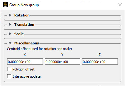
There are three options in this section.
Centroid Offset
When the rotation and scale portions of the transformations are applied, by default they are applied about the point 0.0, 0.0, 0.0 in model space. In the case of rotation in particular, this can result in rotation about an undesirable location. Consider a wheel with its center located at 2987, -1514, 266. The default rotation will be about a point some distance from the center of the wheel. One option is that one could put the wheel in its own group that translates -2987, 1514, -266 and then apply a rotation transform to a group above that group. This scenario is fairly common, so it has been built into the group transformation. In the Miscellaneous section, one can specify a Centroid offset used for rotation and scale' (in our example, enter 2987, -1514, 266). With this set, the rotation and translation will be applied about this point instead.
Polygon Offset
Many models have coincident geometry, which are parts that have the exact same nodes and polygons, for example a fluid inside of a container. The display of these polygons can look rather odd in many cases, particularly when the one or more of the parts are translucent (for example, a translucent fluid inside a solid container). The Polygon offset option specifies that parts which are children of this group will be drawn slightly behind parts that are not in groups with polygon offset set.
It can be important to offset the correct part to get the desired behavior. For example, in the case of a translucent fluid inside of a container, you would put the fluid in a group and set this polygon offset to draw the fluid slightly behind (inside) the container. Setting the container polygon offset would cause undesired behavior as it would slightly offset the container inside of the fluid.
Surface restricted particle traces along the inside surface of the container should be grouped and offset so that they are moved slightly behind (inside the container). Conversely surface restricted particle traces along the outside of a surface should not be offset: rather the surface itself should be offset in this case so that it is moved slightly behind the external particle traces.
Or, consider two identical clips R and B colored red and blue respectively with R placed in a group with Polygon offset enabled. Now, B will always be drawn in front of R, no matter what the viewing angle. If B is made translucent, R will become visible through B.
Interactive Update
By default, the graphics rendering is only updated when the user releases the mouse when dragging on the various sliders. This works well for large models, but for smaller models, checking this box will update the graphics rendering dynamically while the various manipulation sliders are dragged.
Other Options for Part Transformation
Be aware that EnSight includes a number of Other Options for Part Translation, Rotation And/Or Scaling of EnSight geometry.