


The following topics are included in this section:
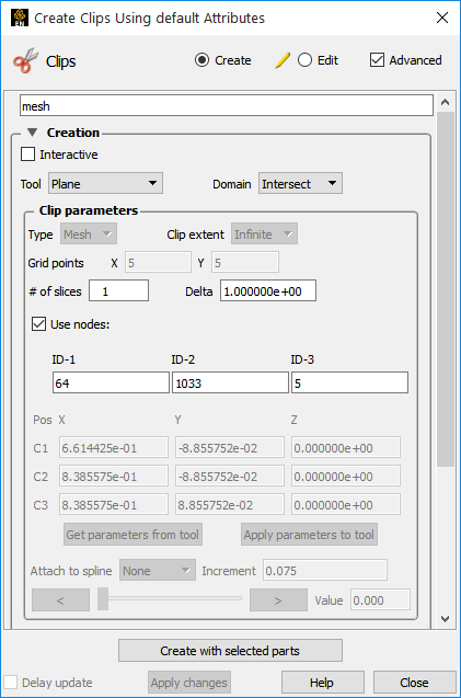
You can specify three nodes on a plane (using their node ids) and clip in an infinite manner. This method of producing a plane clip has the added benefit that the plane will stay tied to those three nodes even if it is a changing geometry model. This method requires the use of the Clips Feature panel.
Select the parent part in the Parts list.
Click on the Clip icon to bring up the Feature Panel.
Click on the toggle.
Enter the id for three nodes that lie on the desired plane.
Click .
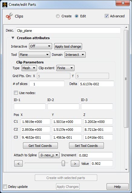
A Clip created with the Plane tool may be attached to a defined spline.
Create a spline (see Use the Spline Tool).
Now, create a clip plane as previously indicated then open the section.
Attach the plane clip to a spline by selecting the desired spline from the pulldown in the Clip Plane Feature Panel.
Adjust the plane clip location (0 to 1) via the Value input field or the slider.
By default, clipping planes (based on the plane tool) are calculated based on the resolution and topology of the underlying mesh (parent part(s)). Clipping planes can also be calculated using a regular sampling of the mesh. Such a clip is called a grid clip and is typically used for clipping unstructured meshes where element volumes vary widely. Creating vector arrows on a grid clip typically yields a more useful visualization than on a standard mesh clip.
Since a clip does a re-sampling of the existing mesh, if the mesh has no elements, the clip will appear empty or with holes. There is the option to create a clip, which will create nodes and elements for the clip part even if the parent mesh does not have corresponding elements.
By default, clipping planes extend to the bounds of the parent part. A clipping plane can also be restricted to the bounds of the Plane tool.
To change an existing clipping plane to a grid clip or to have finite extent:
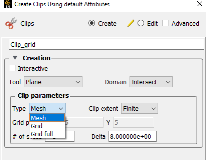
Double-click the desired clipping plane part in the Parts list.
To change to a grid clip, select Grid from the Plane Type pull-down.
To change to a finite-extent clipping plane, select Finite from the Clip extent pull-down.
Although you can interactively sweep a clipping plane (based on the plane tool) through a volume, it is sometimes desirable to have EnSight automatically calculate a series of clipping planes for you. These can then be replayed (as fast as your graphics hardware will permit) using EnSight's Flipbook Animation facility. The flipbook can animate a series of clipping planes using a starting and ending position for the Plane tool. You can also use the Keyframe Animation facility to animate clipping planes.
For a description of calculating a series of clipping planes with the Flipbook, see Create a Flipbook Animation. For more information on keyframing, see Create a Keyframe Animation.
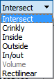
A plane can be used to create parts which are the result of a cut of its parent domain into front (inside) and or back (outside) parts. These parts contain valid elements of the same order as the original domain parts. For example, a plane front cut of a 3D cube model part will include all of the 3D elements in front of the plane tool. Cutting can be used to slice away portions of a model that are not needed or to create animation effects such as opening closed regions to view the interior. Note that the parent part is made invisible so that you can see your cut part.
Select the desired parent parts in the Parts list.
Click the Clip icon.
Select the Plane Tool.
Set the Domain to Inside, Outside, or In/Out (both inside and outside).
Hit the button.
The parent part will be made invisible and your cut part will appear.