


The following topics are included in this section:
EnSight provides six distinct types of variables:
|
Constant |
A constant variable is a single value. Constants
do not vary across a part although a constant can vary over time.
Examples include |
|
Constant per part |
A constant per part is a single value per part. Thus the value does not vary within a given part, but can be different for each part. Examples include things like area, volume, max of a scalar, etc. |
|
Scalar |
A scalar variable is a set of values: one for
each node or element of the applicable part(s). Examples include
|
|
Vector |
A vector variable is a set of values: three (the
X,Y,Z components) for each node or element of the applicable part(s).
Examples include |
|
Tensor |
A tensor variable is a set of values: six (if
symmetric) or nine (if asymmetric), for each node or element of the
applicable part(s). Tensor variables can be represented by Tensor Glyphs
directly, and within the variable calculator eigenvalues, eigenvectors,
determinant, |
|
Complex |
A complex variable, which within EnSight can be either scalar or vector, includes the real and imaginary portions of the values. The variable calculator allows the user to compute things like modulus, argument, transient response, etc. |
Variables are either given (read from the dataset or automatically provided by EnSight) or computed (derived from existing variables during an EnSight session). The variable type and whether it is given or computed are shown in the Variables list panel by looking at the Computed column. The Location column will tell you if a variable is node or element based.
Every non-constant variable (both given as well as computed) has an associated color palette that defines the mapping from variable values to color. These palettes can be edited to change the mapping (see Edit Color Palettes for details). The value of a constant variable can be displayed as a text string in the Graphics Window (see Create Text Annotation for details).
For time-dependent data, calculated variables will automatically recalculate when the current time step is changed.
Derived variables are easily created using the Variable Calculator under Extract Boundary Layer Variables. To create new variables:
Click the Variable Calculator icon in the Feature Icon Bar to open the Calculator tool box. There are by default three tabs (and usually a fourth as you can see). The left mouse icon is for Predefined functions, the icon with the pencil is for Build your own functions, the third tab, Variable information, is used for modal variable feedback. Then multiple other user defined tabs might exist with various functions. The Sum of F tab is a user defined tool distributed by default. It finds the summation of forces and moments.

Select the desired tab to either use predefined functions or define your own equation using math operators and functions.
Predefined functions Tab:
You can search for a function name or find the function in the list. When you select a function, the Variable Name field (at the top of the section) is loaded with the name of the function. This will be the name of the variable as seen in the Variables list. You can change this name by entering a new name (and pressing Return).
A description of the function parameters appears directly below the function list.
In the Predefined function parameters section you are presented with the required inputs to the expression. For each required input you are presented with the valid choices. For example, in the function in the figure at right, density can be either a floating point value or it can be a scalar. If you wish to specify a scalar you would click on the radio button and find the required scalar in the pulldown list (which will only be showing you scalar variables). If you wish to enter a floating point value you would enter it into the field that currently indicates “enter float value” by double clicking and overwriting it with the appropriate value.
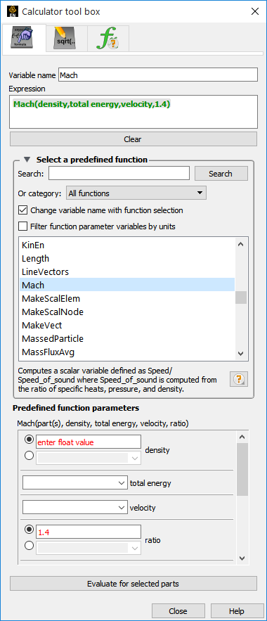
When all of the parameters have been set make sure you have the correct parts selected in the Parts list then click on the button.
Define equation Tab:
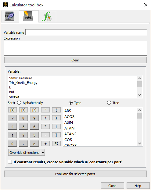
Alternatively, you can build your own equation by selecting variables, math functions, operators, and numbers as desired.
Once you have the desired equation in the Expression field, and a name in the Variable name field - make sure you have
The correct parts selected then
Toggled on the Constants per Part if your result will be a constant and you want a value defined on each part. The default is off, which is a single case constant.
Click .
The following examples demonstrate usage of the variable
calculator. In each case, first enter a name in the Variable
Name field then click on the interface buttons or list entries or
type directly into the Expression area. The examples below assume that
Analysis_Time (a given constant variable if the dataset is
transient), pressure, density, and velocity are all existing, active
variables.
| Expression | Description and How to Build |
|---|---|
| -13.5/3.5 |
A simple constant. To build, either type the text on the keyboard or click in the Calculator keypad. |
| Analysis_Time/60.0 |
A constant variable. Assuming the solution time was given in seconds, this expression will provide a variable giving the time in minutes. To build, select Analysis_Time from the Active Variable list and either type or click /60.0 |
| velocity*density |
Momemtum - a vector variable. velocity To build, select from the Active Variable list, click or type * and select density from the Active Variable list. |
| SQRT(pressure[73]*2.5) + velocity[X][73] |
Square root of ( pressure at node 73 * 2.5 + the X component of velocity at node 73) To build, select SQRT from the Math function list, select pressure from the Active Variable list, click or type [73]*2.5 )+, select velocity from the Active Variable list, and click or type [X][73] |
| velocity^2 | You have to be careful here. velocity^2 is NOT equal to DOT(velocity,velocity). A vector * vector in EnSight is performed component-wise (x-component * x-component, y-component*y-component, and z-component*z-component). The magnitude of this expression is SQRT(x-component^4 + y-component^4 + z-component^4) which is NOT the square of the magnitudes. If you are looking for a scalar result for the square of the velocity, use DOT(velocity,velocity), or, for velocity magnitude, use RMS(velocity) or SQRT(DOT(velocity,velocity)), or SQRT(velocity[x]*velocity[x] + velocity[y]*velocity[y]+velocity[z]*velocity[z]). |
| pressure{19} |
Scalar variable equal to pressure at time 19. This variable will not change if the current time step is changed. To build, select pressure from the Active Variable list and click or type
{19}
|
| MAX(plist, pressure) |
Constant variable equal to the maximum value for pressure over all nodes of all parts in plist To build, select MAX from the General function list and follow the instructions in the Feedback area. |
| (pressure/max_pres)^2 |
Scalar variable equal to squared normalized pressure To build, first calculate the MAX constant variable as described in the preceding example, here named max_pres Click or type ( select pressure from the Active Variable list, click or type / select max_pres from the Active Variable list, and click or type )^2 |
Since EnSight can compute only one variable at a time, one must break down involved equations into multiple smaller ones, using temporary or intermediate variables.
Calculator limitations include the following:
The variable name cannot be used in the expression. The following is invalid:
temperature = temperature + 100
Instead use:
temperature2 = temperature + 100
The result of a function cannot be used in an expression.
(pressure / MAX(plist,pressure) )^2
Instead use two steps. Define p_max as:
MAX(plist,pressure)
then define norm_press_sqr as:
(pressure / p_max)^2
Created parts (or changing geometry model parts) cannot be used with a time calculation (using { }).
Calculations occur only on server-based parts. Client-based parts are ignored, and variable values may be undefined.
For information on the arguments (and equations), see Predefined functions or Math Functions under Variable Units in the Ansys EnSight User Manual.
Rather than having to individually create the various common CFD variables, EnSight can automatically make them available for use if the appropriate basis variables and constants have been provided. This can be accomplished after loading the model with the Extended CFD Variable Settings Dialog:
Right click on any variable in the Variable list then choose from the pulldown.
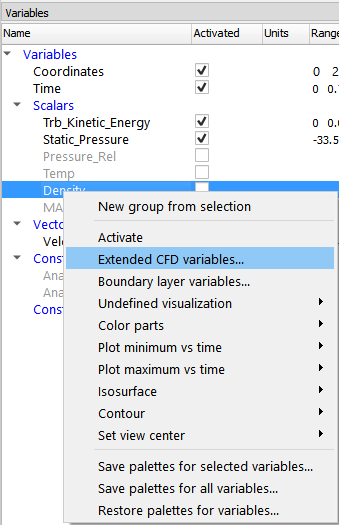
Select the variable name in the list and then click the appropriate button.
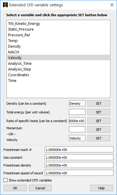
For example, select Density in the list and then click the button to right of the Density field.
After all variables and constants have been specified, click Show Extended CFD Variables.
Click .
The common CFD variables will now be listed in the main variables list.
Note: They will NOT actually be computed until activated.
If you have a “standard” PLOT3D Q file, Extended CFD variables will be shown by default when you read your data.