


For product advisories and changes to Discovery features that existed in earlier releases, see Discovery Product Advisories.
Areas where you will find new capabilities and enhancements in Discovery include:
- 2.1. Fluid Flow Simulation
- 2.2. Structural Simulation
- 2.3. Electromagnetic Simulation
- 2.4. Contacts and Interfaces
- 2.5. Solution and Optimization
- 2.6. Meshing
- 2.7. Modeling Tools
- 2.8. Sheet Metal
- 2.9. Materials
- 2.10. User Interface Enhancements
- 2.11. User Settings Summary
- 2.12. Results
- 2.13. Import/Export Support
- 2.14. Performance
- 2.15. Extension Builder
- 2.16. Interactive Tours
- 2.17. Installation and Licensing
- 2.18. Ansys Discovery Technology Showcase: Example Problems
- 2.19. Ansys 3D Design Verification Manual
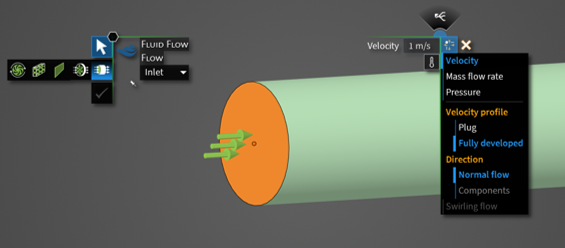
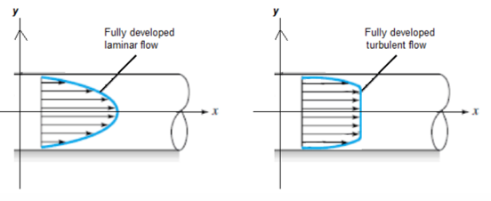
A new option is available to specify a fully developed profile (in Refine) for circular velocity inlets. The laminar or turbulent inlet profile is determined from the turbulence model.
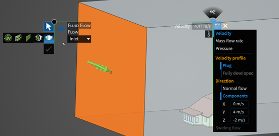
A new option to specify the X, Y, and Z components for velocity inlet is available. It provides additional control for defining the inlet flow direction.
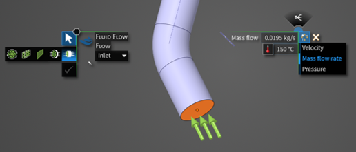
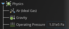
Mass flow rate specification at a flow inlet is now supported in compressible flow simulations in Explore. The new capability to combine mass flow inlet with the ideal gas law provides additional flexibility for defining flow conditions for subsonic gas flows or flows with large temperature variations.
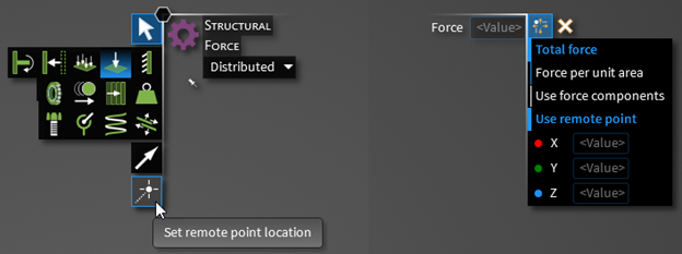
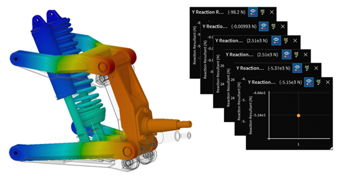
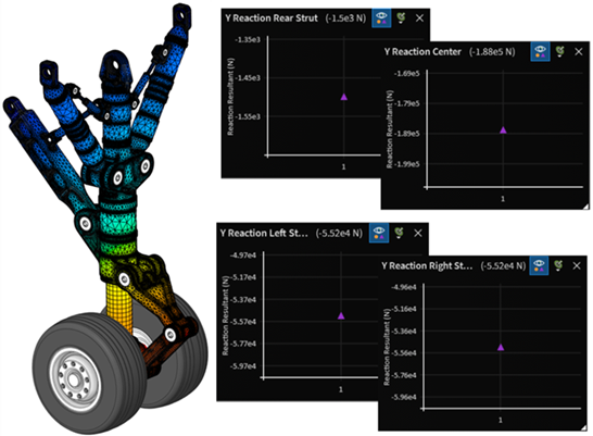
You can now select a point, edge, face or body to define remote points for structural conditions, including force, mass, and displacement. The centroid of the geometry selection defines that remote point location. This option improves the workflow for the remote force, remote mass and remote displacement conditions.
New conditions for voltage and current were added. Voltage and current can only be applied to faces. Circuit and mode port are disabled when voltage/current is selected.
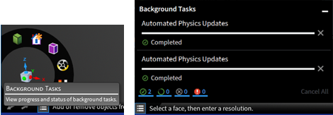
To add voltage or current: select one or more faces. Press Enter.

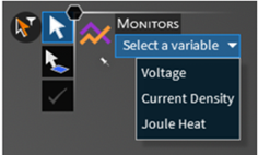
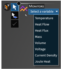
New monitors for electric simulations were added for Voltage, Current Density and Joule Heat.
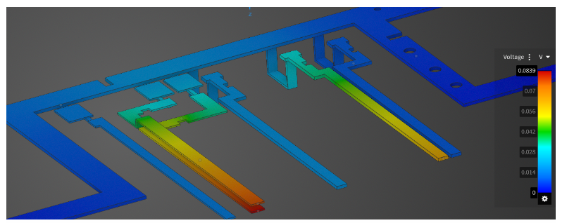
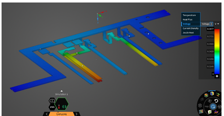
New contours were added for electrical simulations to display Voltage, Current Density, or Joule Heat.
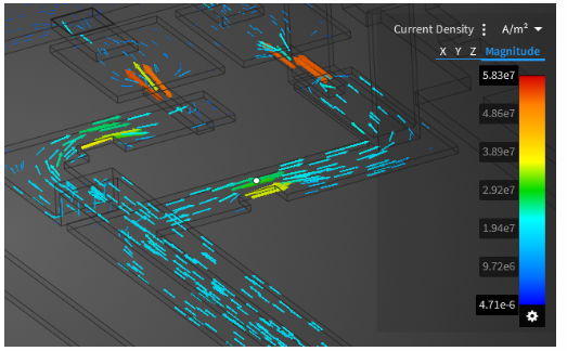
New vectors were added for electrical simulations to display Current Density.
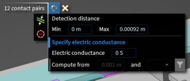
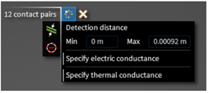
Electrical Conductivity were added as a new material property for Electric Simulation. Additionally, Electrical conductivity is available to be user-defined on contacts using the Contact Review Tool.
The recently introduced Electric conditions can be used along with the existing Thermal conditions. The integrated Thermal-Electric Simulation provides settings, monitors, contours, and various results visualization options from both the existing Thermal Simulation features and the new Electric Simulation features
For Thermal-Electric Simulations, both Electrical conductivity and Thermal conductivity are available to be user-defined on contacts using the Contact Review Tool.
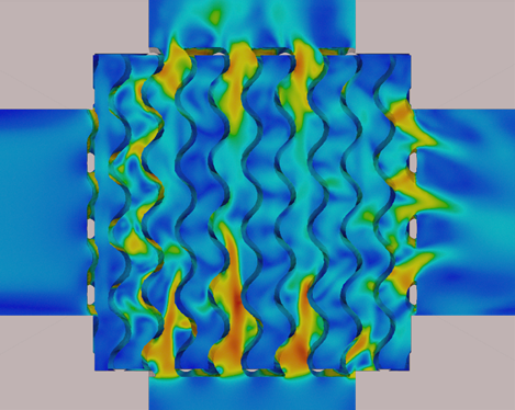
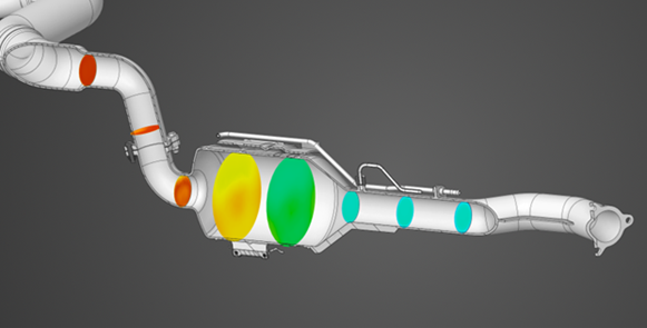
In Explore you can now simulate fluid-solid (conjugate) heat transfer using faceted geometry with automatic interface detection. This new capability enables the evaluation of fluid and thermal performance of high efficiency gyroid heat exchangers.
You now have the option to specify a Face overlap allowance for fluid-solid interfaces, useful when you have very small contact points, especially near curved edges. This option defines the percentage that faces are allowed to overlap during interface detection.
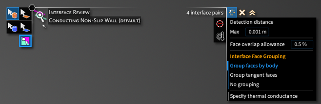
The default for this field is set in the Physics Settings.
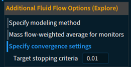
In Explore, you can specify the convergence settings by entering the Target stopping criteria. Solution convergence is achieved when the percentage change in the solution variables is less than the specified tolerance. A default value of 0.01 (or 1%) is used in the application.
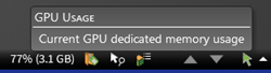
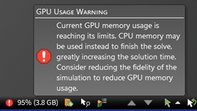
The ability to monitor your GPU memory usage while solving is now available in Explore. Additionally, for fluid flow simulations, you can monitor GPU memory usage in Refine when using the LiveGX GPU solver. Discovery displays the current GPU memory usage in the status bar. It will also warn you if your current simulation exceeds your GPU's available memory. Excessive GPU memory usage can lead to instability or dramatically slower solve times due to paging to system memory.
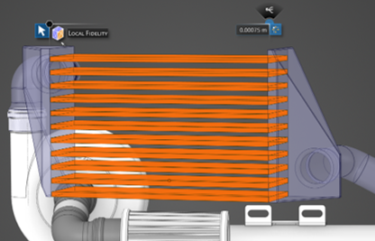
Local fidelity for fluid flow simulations in Explore can now be applied to bodies, including cutter bodies, as well faces. As a result, thin fluid channels and small components are easier to capture.
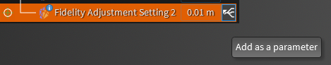
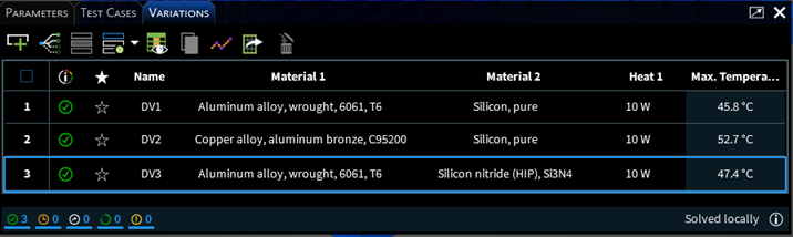
Defined variations and parameter studies can now be applied to local fidelity inputs.
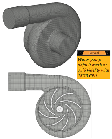
In Explore, GPU meshing is now the default meshing algorithm for all fluids and fluid-solid heat transfer simulation with or without local fidelity. Additionally, fluid simulation in Explore now includes the ability to apply a local fidelity on bodies, which can be combined with local fidelity on faces. The new GPU meshing algorithm combined with local size controls makes it easier to discretize thin fluid channels and small components, while simultaneously improving accuracy with a more efficient use of GPU memory.
Note: Many modeling tools are common between Discovery and SpaceClaim, although implementations may differ depending on product.
Additional modeling documentation that was originally developed for SpaceClaim is available in the Discovery Documentation's Table of Contents. This change provides easier access to detailed conceptual and reference information about modeling functionality in Discovery.
You may notice anomalies in the modeling documentation when accessed from Discovery. Improvements are ongoing.
Clearance Detect. The upgraded Clearance Detect feature now operates faster to more effectively pinpoint gaps within the model.
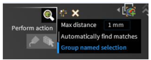
Group Named Selection. A new tool option to Group named selection was added to the Detect tool. This option is only used if you choose to create a named selection from the HUD. Select it to create a single named selection for the detected areas. Deselect this option to create a named selection per detected area.
Detect Sweepable Bodies. The Detect HUD now includes a tool for detecting bodies that can be swept. Sweepable bodies have free (unstructured) source and target faces opposite each other and mapped faces on the perpendicular sides between. They can be filled with an all hex and/or prism mesh that is interpolated between the source and target faces. This feature helps you prepare your model for hex meshing and reduces the need to return to Discovery from a downstream tool.

Additional options are now available for the following modeling tools:
The Extend tool in the Prepare tab has a new Create body option. It will create a weld body between two surfaces.
The Enclosure tool in the Prepare tab has a new Subtract from enclosure option.
The Point tool in the Design tab allows you to Use precise location.
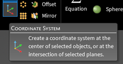
In the Design tab, Origin was renamed to Coordinate system.
The performance of the Share tool has been improved at Release 2025 R1.
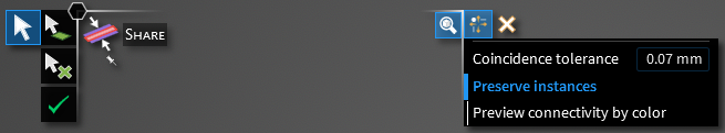
Use
 to preview coincident topology based on the coincidence tolerance and
other options selected.
to preview coincident topology based on the coincidence tolerance and
other options selected.You can now directly share topology without previewing the coincident topology. This improves performance especially for large models where the preview may consume significant time.
The Beams feature now includes the following new functionality to expand and ease the specification of beams:
You can now select bodies, faces or edges to assign beams. The Discovery application will create curves on all edges of selected geometry and assign beams.
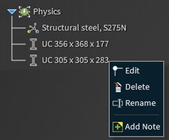
You can now remove a beam profile by right-clicking it in the physics tree.
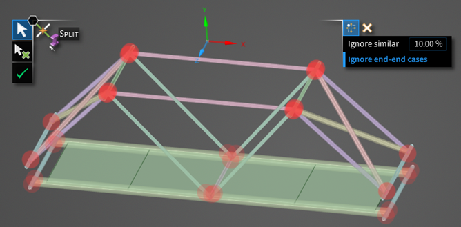
You can now use the Split tool to find connections between solid (extracted) beams, where the end of one beam lies somewhere in the middle of another beam.
For any connections found, the beam with the smaller cross section is split by the beam with the larger cross section. Beams with the same cross section are not highlighted. Cross sections that are not the same but are of similar size are also disregarded. You can specify the percentage size difference used to consider any two beams to be similar. You can also choose to ignore beams that meet at end points.
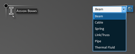
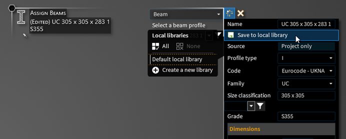
You can now create a new beam definition, rather than relying on standard library definitions. You can either select and then edit a standard library definition, or select a beam type and modify default values populated based on the selected type.
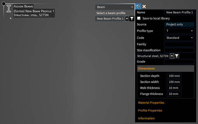
You can now select a type for your beam. Types include Beam, Cable, Spring, Link/Truss, Pipe, and Thermal Fluid. The type can be applied to any beam. This attribute is then passed on to downstream applications.
The Sheet Metal tab in Discovery contains tools for working with sheet metal designs.
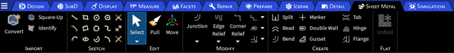
You can:
Create or import sheet metal designs.
Sketch new sheet metal parts and edit or modify existing sheet metal designs.
Add sheet metal features such as bends, tabs, or hinges to your design.
Unfold the sheet metal component and view the unfolded component in a new component tab as a top view with its overall dimensions.
Sheet metal settings are available for setting defaults. You can additionally modify the thickness, inner radius, and other sheet metal properties in the Properties tab of the Advanced Selection window.
The following enhancements related to materials are available in Discovery 2025 R1.
Materials Data for Simulation (MDS) is available through an optional license that provides access to simulation-ready materials data for a broad coverage of materials classes, enabling engineers to create more accurate simulations with trusted data. For easy access, MDS is embedded directly into Discovery and currently contains 771 materials covering a wide range of material classes.
| Material Class | Count |
|---|---|
| Ceramics | 47 |
| Composites | 37 |
| Fluids | 37 |
| Foams | 16 |
| Glasses | 15 |
| Honeycombs | 3 |
| Magnets | 27 |
| Metals - ferrous | 153 |
| Metals - non-ferrous | 226 |
| Polymers | 176 |
| Woods | 34 |
| Total | 771 |
Developments for 2025 R1 have focused on continuing to provide accurate and reliable simulation-ready materials data with standard updates to point and curve data.
There are no new materials in the 2025 R1 release of MDS, but some data values have been updated.
The Materials Data for Simulation (MDS) Sample library provides 39 materials free of charge to Discovery users with basic room temperature point data for mechanical and thermal properties.
There are no new materials in the 2025 R1 release of MDS, but some data values have been updated.
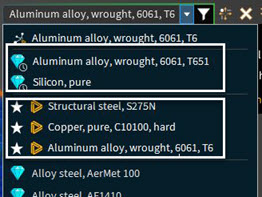
Some dropdown lists that contain many items now display favorites and recently used at the top of the list to improve usability.
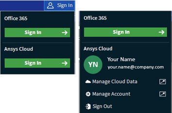
A new sign-in panel includes access to Microsoft 365 as well as Ansys Cloud. If you are logged into Ansys Cloud, you can access the cloud portals to manage your cloud data and cloud account.
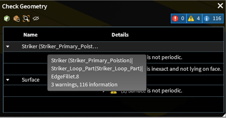
The Check Geometry panel truncates long names but the full name is displayed in a dynamic tooltip along with a count of associated errors, warnings or informational messages.
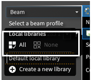
Some assignment tools allow advanced selection with All or None.
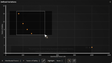
With Zoombox you can box-select an area on variation charts to zoom in and examine it closely. When you're done, click Reset Zoom to return to the original view.
Additionally,
Changes to visual padding may improve the legibility of visual elements for some users.
Improvements to messages and notifications continue in this release.
Improved drag-and-drop file functionality has a larger drop area and greater flexibility when opening or inserting files.
Tree improvements include:
The trees can now be moved out of the main UI.
Reordering of some nodes within the model tree is now possible.
Cut plane node now differentiates with naming and different icons between a plane and a cut plane created by Cut plane in the Results arc.
A lock icon shows on the component parent node when all subcomponents are locked.
A feather icon displays on the component parent node when all subcomponent bodies are lightweight.
Changes and additions have been made to Licensing settings, which were moved from Advanced to their own Licensing section:
Discovery license: You now choose Discovery Enterprise, Discovery Premium, or Discovery Pro.
Check for lower license if requested is unavailable: Select this new option if you want to check for a lower level license if the license requested by the Discovery license option is unavailable.
Alternate license: Select an Alternate license for flagship products.
Check for Discovery Pro license prior to alternate license: Select to check whether you have a Discovery Pro license before checking for an alternate license. This option is applicable only when Discovery license is set to Discovery Pro, and an Alternate license preference is specified.
Also see Installation and Licensing for broader changes related to licensing.
In the Physics Settings, you can now specify a default for the Face overlap allowance in fluid-solid interfaces. For more information, see Face Overlap Allowance.
Generate default scenes: You can control the generation of default physics saved scenes globally through the Settings panel. There you can also set the default view orientation for scene capture. Options include home, isometric, trimetric, right, left, top, bottom, front and back.
A new section was added for sheet metal settings. Set Basic and Relief defaults, settings for Export, and for Lines and Colors for Layers and individual sheet metal elements.
Maximum undo steps: Undo/redo improvements include a scrollbar to navigate the undo/redo list. The number of items in the undo/redo list is customizable but the maximum will depend on local display settings. Set the Maximum undo steps in Advanced Options on the Advanced tab of the Settings panel.
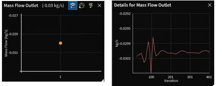
Detail monitors and standard monitors are now based on node values. Prior to this release, the detail monitor value was a face-based result while the standard monitor value was a node-based result.
Detail monitors are now available in Explore for reviewing engineering quantities of interest as a function of solution iteration. Use monitor details to judge solution convergence in steady-state fluid flow and fluid-solid heat transfer simulations.
Enhancements have been made for displaying contour results on planes, which improve the speed of display and robustness. Contour results on planes are shown in Explore and Refine modes for all physics except electromagnetics. Planes for LiveGX are also supported, with results being updated as the geometry changes.
Saved scenes has expanded functionality to generate scenes automatically for most physics conditions. You can control the generation globally through the Settings panel or, for a given document, through the Scene dropdown list in the Simulation tab. You can also set the default view orientation for scene capture.
In the Explore stage, reaction resultants are now available for remote displacements, which enables you to review static equilibrium for structural models.
The import and export of Ansys Stride (*.stride) files is now supported.
The following have been deprecated at Release 2025 R1:
- Import Support
ACIS - *.asab, *.asat formats are not supported.
Revit - *.rvt, *.rfa files are not supported.
- Export Support
ACIS
Options for exporting Part manufacturing information have been deprecated.
Only version V5 is supported for export.
Discovery Release 2025 R1 continues to address reported issues in application performance and modeling responsiveness. You may notice performance improvements in all stages from refresh rates to solution rendering, including:
better performance when working with large models,
better overall progress and messaging for modeling operations, add-ins and customization,
improved performance for models in the Model stage,
improved and interactive background task management, and
better overall performance and fewer unresponsive events.
Performance is improved when working with large models. You can:
Convert geometry imported or created in Discovery to lightweight using the Convert to Lightweight option in the context menu from the Model tree.
Convert lightweight geometry to heavyweight using the Convert to Heavyweight option in the context menu from the Model tree.
View the lightweight state on the component parent node when all subcomponent bodies are lightweight.
Open and save lightweight files for large models as Ansys Stride (*.stride) files.
Also worth noting is Discovery’s improved hardware support with the ability to run on a wider array of hardware configurations. Discovery will attempt to run with the existing hardware configuration. If resources are inadequate to solve simulations in Explore or Refine, Discovery will, at a minimum, run in the Model stage. This is particularly relevant for remote sessions.
Discovery is now more responsive when using modeling tools on complex geometries. A progress message box may now display so the current operational status is clear. Also, the SpaceClaim API progress tracker will now show a progress message box if the add-in requests it.
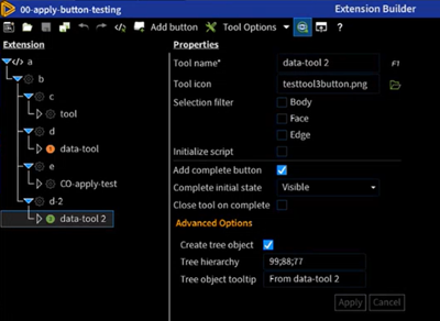
The Extension Builder allows you to add customizable objects to tools, which will then appear in the Extensions tree.
When adding a new tool, select Advanced Option from Add Button > Properties Panel. This option enables you to create a tree object, organize it into a hierarchy under the extension entry object, and add a tooltip.
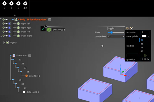
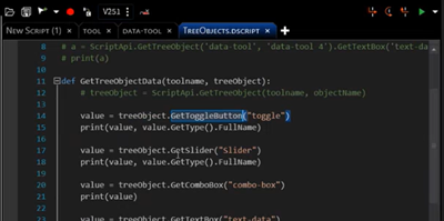
Multiple customizable objects from various tools can be added to the same tree, where they can be edited and referenced in scripts. For example, in previous versions, applying four different forces required four separate tools. Now, you can add multiple forces within the same tool.
Links to Ansys Learning Hub have been added to the end of all the tours to provide subscribers with access to simulation courses. Those with no subscription will use a different link to access the courses on Ansys Innovation Space.
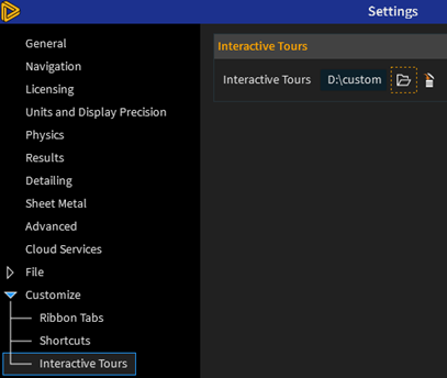
In the Settings panel, under Customize > Interactive Tours, you can load customized interactive tours that you or your organization have created. Browse to the folder that contains the customized interactive tour resources. You can access the custom tour from the File Menu > Home Page under the Custom Tours tab.
Discovery Learn Concepts have been added to the Static Structural interactive tour. They explain engineering concepts to help you learn the why along with the how-to. Click the embedded links in the tour to learn more about the physics used in the simulation.
If you install the Discovery product package, it contains a full installation of Discovery. If you install Discovery as a component of another Ansys product package, such as an Ansys Fluids or Ansys Structures package, you may now choose between a full or reduced Discovery installation. The reduced option is suitable for preprocessing only. It does not include the Fluent or MAPDL solvers, thereby limiting the use of the Refine stage as well as impacting physics transfer downstream.
Discovery has moved to a Pro, Premium, Enterprise (PPE) licensing scheme. The former Discovery Modeling is now Discovery Pro, the former Discovery Simulation is now Discovery Enterprise, and a new mid-tier offering, Discovery Premium, is now available.
Capability Levels and Licensing Requirements Description Discovery Enterprise Provides access to all geometry modeling and simulation capabilities, including advanced capabilities such as fluid-solid heat transfer, radiation, and electromagnetics physics.
Requires disco_level1 + disco_level2 + disco_level3 licensing increments.
Permits all modeling operations.
Permits structural, fluids, and electromagnetics solves in the Explore stage and electromagnetics and fluids solves in the Refine stage.
For structural, provides access to solving in the Refine stage but an appropriate flagship solver license is also required.
For fluids solves in the Refine stage, you can use the LiveGX solver, which is the default and does not require an additional flagship license. If you disable the LiveGX solver, an appropriate flagship solver license is also required.
Electromagnetics is supported in Discovery Enterprise only and does not require an additional flagship license.
Discovery Premium Builds on Discovery Pro by adding access to advanced modeling capabilities and additional structural and thermal physics, as well as fluids physics.
Requires disco_level1 + disco_level2 licensing increments.
Discovery Pro Provides access to most geometry modeling capabilities, plus support for entry level structural physics.
Requires the disco_level1 licensing increment.
Permits most modeling operations.
Blocks creation and editing of physics objects other than entry level structural physics.
Blocks solving other than entry level structural physics.
Permits read-only access to the Explore and Refine stages for all remaining physics.
Permits read-only access to results and post-processing for all remaining physics.
Enables you to run your choice of Discovery Modeling, SpaceClaim, or DesignModeler. However, you may run only one of these products at a time.
Also see Licensing for information about licensing options on the Settings panel.
For 2025 R1, the following examples have been added:
Planar Inverted-F Antenna Behind a Radome
Parallel Flange Channel and Plate Bolted Connection
Ahmed Body Drag Coefficient
Gyroid Heat Exchanger Thermal Performance
For ease of access to the manual, a link has been added from Discovery's Home Page to the Ansys Discovery Technology Showcase: Example Problems manual in the Online Help.
You can download project files directly from the Ansys Discovery Technology Showcase: Example Problems manual.
For 2025 R1, the following test cases have been added:
Steady-state Laminar Flow
Laminar Flow Between Rotating and Stationary Cylinders
Steady-state Thermal-electric Simulation
Centerline Temperature of an Electrical Wire
NAFEMS Benchmarks
P09 - Free Vibration Benchmarks, Abbassian, F., Dawswell, D.J., and Knowles, N.C.
P09-T4 - Cantilever with Off-center Point Masses
P09-T6 - Circular Ring – In-plane and Out-of-plane Vibration
P09-T15 - Clamped Thin Rhombus Plate
P09-T33 - Free Annular Membrane
You can download project files directly from the Ansys 3D Design Verification Manual.